

Continuous kneading device and kneading system using the same
A kneading and continuous technology, applied in the field of kneading systems and continuous kneading devices, can solve the problems of poor quality and excessive heat release, and achieve the advantages of suppressing heat release and deterioration, cost and manufacturing time, and improving productivity. Effect
- Summary
- Abstract
- Description
- Claims
- Application Information
AI Technical Summary
Problems solved by technology
Method used
Image

Examples
no. 1 example
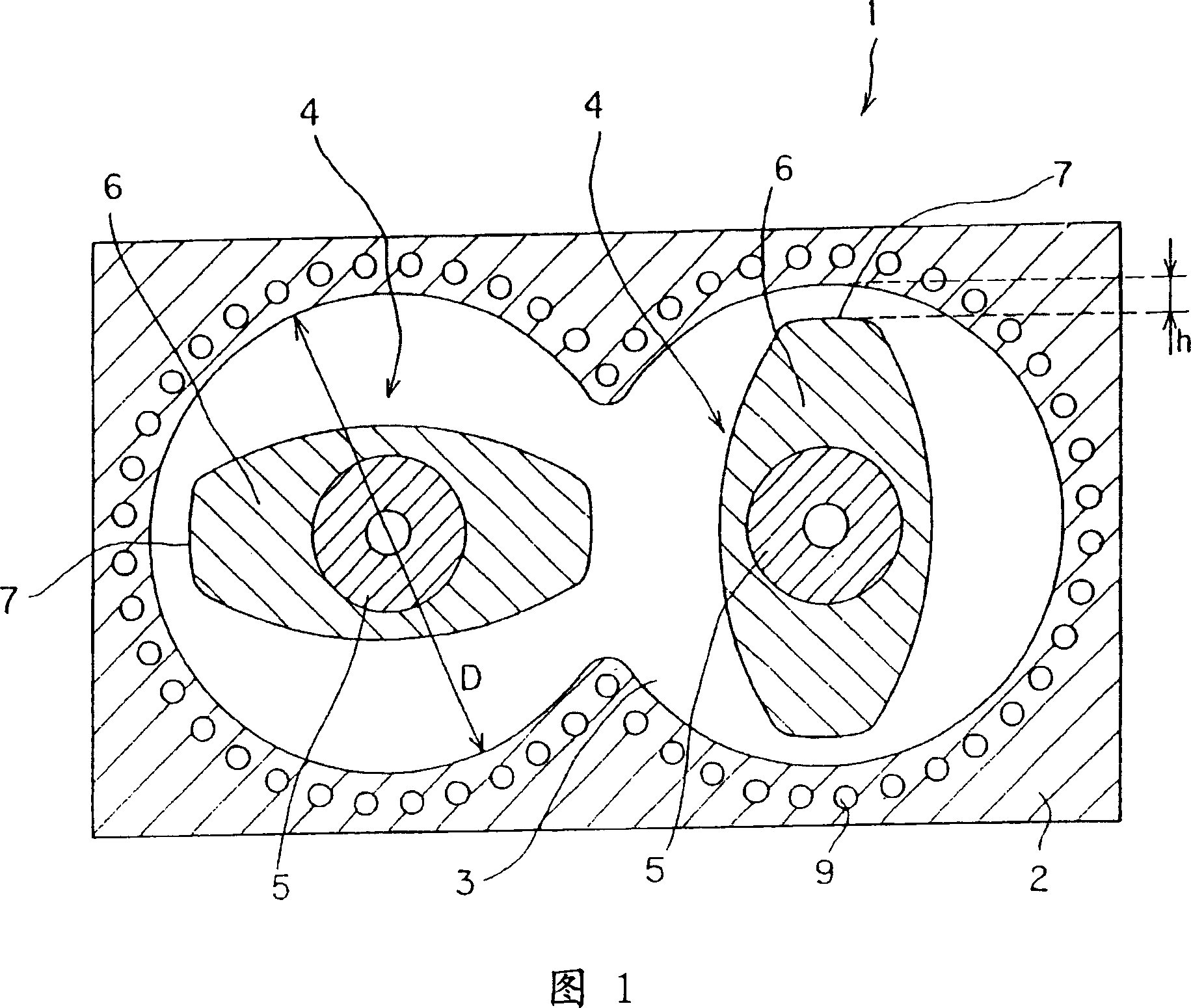
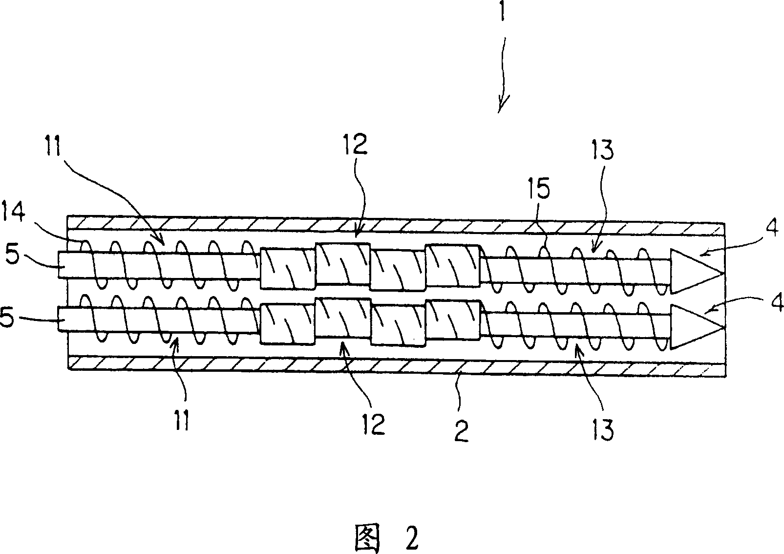
[0064] Now, embodiments of the present invention will be described for illustrative purposes based on the drawings. Fig. 1 is a schematic cross-sectional configuration diagram showing an essential part of a continuous kneading apparatus according to a first embodiment. Fig. 2 is a schematic inner plan view of a twin-screw kneading extruder which is a continuous kneading device according to the first embodiment.
[0065] As shown in FIG. 2 , the twin-screw kneading extruder 1 according to this embodiment has a pair of parallel screw groups 4 inside the barrel 2 . Generally, the screw group is constituted by a part such as a kneading disc or a kneading disc and a part such as a screw or a combination of a plurality of such parts provided on the outer periphery of the rotating shaft.
[0066] When viewed from the feeding direction of the material to be kneaded, each screw group 4 in the present embodiment includes an extruding section 11 (one end) having a screw fin 14 on the ou...
no. 2 example
[0085] Fig. 4 is a schematic cross-sectional configuration diagram showing an essential part of a continuous kneading apparatus according to a second embodiment of the present invention.
[0086] This embodiment is intended to engage the blade portions 7 on the two shafts (rotation shafts 5, 5) of the first embodiment by arranging the kneading disc in such a way that the trajectories of the two rotating blade portions overlap in front view And improve the mixing performance. Since other features are the same as those of the first embodiment, the same parts and positions as in FIG. 1 are denoted by the same numerals and symbols as in FIG. 1, and repeated explanations are omitted.
[0087] Preferably, the components are arranged such that the engagement between the two shafts is not only possible at the blade portion 7 in the kneading section 12, but also at the screw fins (knife portion in a broad sense) in the extruding sections 11, 13. 14 , 15 , ie over the entire length of ...
no. 3 example
[0089] Fig. 5 is a schematic inner plan view of a uniaxial kneading extruder which is a continuous kneading device according to a third embodiment. The single-shaft mixing extruder 20 shown in this figure and the twin-shaft mixing extruder 1 shown in FIG. 2 have comparable characteristics, except that they differ in the number of shafts and the shape of the tubular barrel 2 . Accordingly, corresponding features of the two extruders are designated by the same numerals.
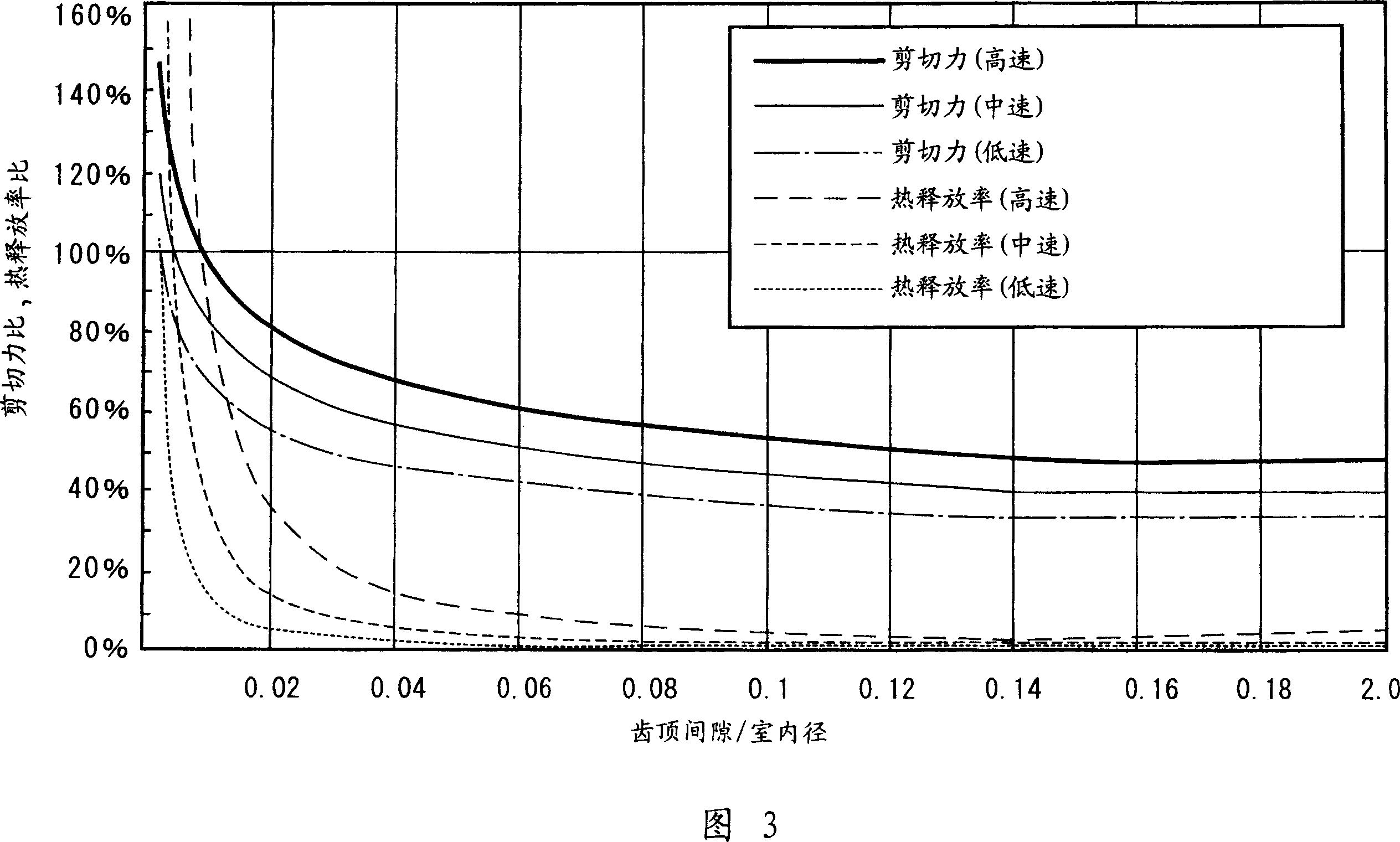
[0090] In the kneading section 12 of this uniaxial kneading extruder 20 , the material to be kneaded is kneaded by the shear force generated between the tip portion (blade portion) of the kneading disc and the inner wall surface of the barrel 21 . Also in this embodiment, h / D within the range of the first embodiment is employed, so that heat release can be remarkably suppressed, and the decrease in shear force τ can be kept small. The life of the device is also extended.
[0091] Also in this embodiment, the ...
PUM
 Abstract
Description
Claims
Application Information