Method for fine adjusting amount of feed of boring cutter tool, and adjustment device

A technology of feed amount and micro-adjustment, which is applied in the field of machining tools, can solve the problems of complex shape of parts, large center of gravity offset, and influence of boring accuracy, etc., to achieve simple shape of parts, small center of gravity offset, and good structural rigidity Effect

Inactive Publication Date: 2007-05-09
邱寿山
View PDF0 Cites 16 Cited by
  • Summary
  • Abstract
  • Description
  • Claims
  • Application Information

AI Technical Summary

Problems solved by technology

This kind of adjustment device will inevitably result in more parts that cooperate with each other and the shape of the parts is more complicated, and the processing is more difficult; and because there is a gap between the linear moving parts, the boring accuracy will be affected if the maintenance and adjustment are not careful; Large displacement is not conducive to high-speed cutting; and because the screw pitch cannot be too small, the fine-tuning is also restricted, and the fine-tuning accuracy of this product is generally difficult to reach 0.01mm substantially

Method used


Image

  • Method for fine adjusting amount of feed of boring cutter tool, and adjustment device
  • Method for fine adjusting amount of feed of boring cutter tool, and adjustment device
  • Method for fine adjusting amount of feed of boring cutter tool, and adjustment device

Examples


Embodiment 1

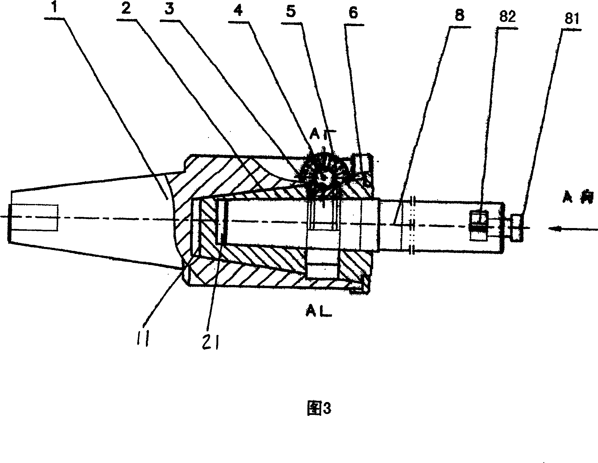
[0038] Referring to Fig. 3, Fig. 4 and Fig. 5, the fine-tuning device for the amount of tool feed in this embodiment is applied to a milling machine. The eccentric taper hole 11 of the body 1 axis. In the eccentric taper hole 11, the rotating cone 2 is installed through the end cap and the compression ring 6 which are threadedly connected with the handle body 1. On the rotating cone 2, there is also an eccentric taper hole 21 deviated from the axis of the rotating cone 2. In the eccentric taper hole 21 of the rotating cone 2 axis, a replaceable tool bar 8 is housed, and a cutter 82 is installed by a fastening screw 81 at the front end of the replaceable tool bar 8 .

[0039] A worm wheel 3 is installed on the rotating cone 2 , and of course the worm wheel 3 can also be directly processed on the outer surface of the rotating cone 2 . The worm 4 is installed on the handle body 1 through two bearing end caps 5 and meshes with the worm wheel 3 to drive the rotating cone 2 to rota...

Embodiment 2

[0044] Referring to Fig. 6-Fig. 9, the fine-tuning device for the feed amount of the tool in this embodiment is applied to a milling machine, and the taper shank of the tool handle body 1 is matched with the taper hole of the milling machine spindle.

[0045] The fine-tuning accuracy can be designed according to the principle. In this embodiment, the worm 4 is designed to make one revolution, and the diameter is reduced by 0.5 millimeters. The rotation and diameter reduction indicator dial 7 on the worm 4 has 50 scale lines, indicating that each grid has a diameter reduction of 0.01 millimeters.

[0046] In this embodiment, in the eccentric taper hole 11 of the handle body 1 , the rotating cone 2 with the taper hole 22 is installed through the pressure spring ring 6 and the anti-loosening cover 61 threadedly connected with the handle body 1 . The axis of the tapered hole 22 coincides with the axis of the rotating cone 2 .

[0047] The incomplete worm wheel 31 in the worm and g...

Embodiment 3

[0055] Embodiment 3 is applied to a machining center machine tool, as shown in Figure 10. The difference from Embodiment 2 is: 1. The taper shank of the tool handle body 1 cooperates with the taper hole of the machining center spindle; There are two forms of rotary reducer.

[0056] Cutter 82 and replaceable cutter bar 8 adopt screw drive, and a straight line moving variable-diameter indicator dial 84 is arranged on the drive screw rod, and indicating line is engraved on the replaceable cutter bar 8.

[0057] Between cutter 82 and replaceable cutter bar 8 can adopt oblique line or linear movement variable diameter, the included angle between the axis of cutter 82 and the axis of replaceable cutter bar 8 is blind hole or through hole design according to processing object.

[0058] Rotary variable diameter is adopted on the tool handle body 1, and the fine-tuning accuracy can be designed according to the above-mentioned principle. In this embodiment, the worm 4 rotates once to r...


PUM


Abstract

A method for trimming the feed amount of a boring cutter features that when the tip of a boring cutter is revolving around the axis of its handle by an eccentric distance, the revolving diameter of said tip can be changed relatively to the axis of handle while the value of changed diameter can be precisely prompted. Its trimming unit has a cutter handle with a conic hole whose axis is shifted from the axis of handle, a rotary body in said conic hole and with another conic hole, an exchangeable arbor installed in said another conic hole and with a cutter, and a worm-gear driver mechanism installed on handle for driving arbor to rotate.

Description

technical field [0001] The invention relates to the technical field of machining tools, in particular to a method and an adjusting device for adjusting the feed rate of a tool, in particular to a fine-tuning method and an adjusting device for the feed rate of a boring tool. Background technique [0002] As we all know, the currently used fine-tuning boring tool bar is composed of a tool handle body with a linear guide rail, a moving body matched with the guide rail, a screw transmission mechanism, a replaceable tool bar, a linear moving variable diameter indicating dial, and a tool fastening tool. Composed of screws, the principle is shown in Figure 1. The technical characteristics can be said to be a linearly movable variable-diameter fine-tuning boring tool bar. path purpose. This kind of adjustment device will inevitably result in more parts that cooperate with each other and the shape of the parts is more complicated, and the processing is more difficult; and because th...

Claims


Application Information

Patent Timeline
Patent Type & Authority Applications(China)
IPC IPC(8): B23Q15/013B23B47/18
Inventor 邱寿山
Owner 邱寿山
Why Eureka
Try Eureka