Apparatus for durable joining of two workpieces having at least one source of energy

A technology of energy source and parts, applied in household components, applications, electrical components, etc., can solve problems such as high cost, achieve low cost, reduce production time, and achieve the effect of synchronous welding

Inactive Publication Date: 2007-05-09
约翰逊电气奥尔登堡有限责任两合公司
View PDF0 Cites 0 Cited by
  • Summary
  • Abstract
  • Description
  • Claims
  • Application Information

AI Technical Summary

Problems solved by technology

[0004] The disadvantage of laser welding is that it requires the use of high-cost laser equipment

Method used


Image

  • Apparatus for durable joining of two workpieces having at least one source of energy

Examples


Embodiment Construction

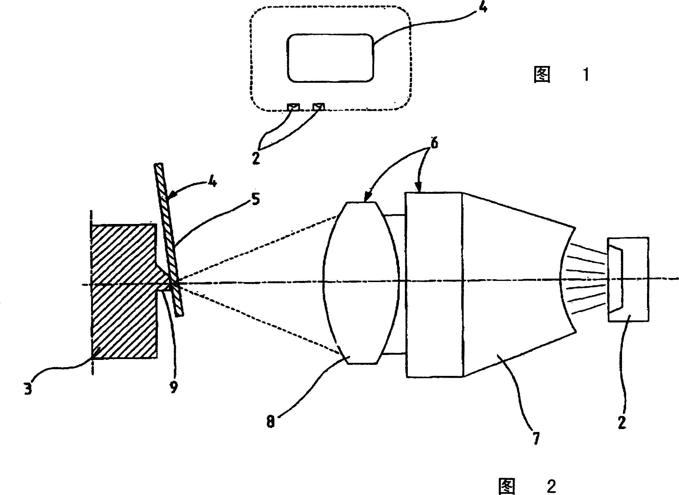
[0018] Figure 1 shows a device according to the invention for the permanent connection of two parts. The cap 4 is shown in plan view in this figure, and this part is likewise shown in FIG. 2 . The cap 4 in FIG. 1 is fixed in a fixture and surrounded by a plurality of LEDs 2 in the form of a frame. The light emitted by the light-emitting diodes 2 is transmitted synchronously to the jig, and the parts on the jig can be welded to each other by means of the light.

[0019] FIG. 2 shows the sockets 3 of the microswitches and the caps 4 of these microswitches. The transparent section of the cap wall 5 in FIG. 2 is matched to a light-emitting diode 2 . Between the light-emitting diode 2 and the cap wall 5 there is installed an optical system 6 for guiding light waves, which comprises an optical waveguide 7 made of glass and a focusing element 8 . The optical system 6 that guides the light waves is spaced from the cap wall 5 and the surface of the stem 3 at a distance that correspo...


PUM


Abstract

The invention relates to a device for permanently joining at least two components, comprising at least one power source for providing energy to bring about the joint.

Description

technical field [0001] The invention relates to a device for permanently joining at least two parts comprising at least one energy source for supplying the energy required to produce the joint. Background technique [0002] A permanent connection can be produced, for example, by soldering or welding. The durability of the connection can be obtained by heating the parts to be joined together in a fractional manner, causing them to liquefy, so that when the parts are recooled, the materials of the two parts can form a mating connection. What is used for heating is an energy source. [0003] Besides electric welding, laser welding is also a well-known method. Laser welding has the advantage over thermal element welding and other welding methods that it does not create mechanical stress on the part and offers a nearly wear-free process because heat transfer is localized. This welding takes place in a contactless manner, and materials of different viscosities can be joined to ...

Claims


Application Information

Patent Timeline
Patent Type & Authority Applications(China)
IPC IPC(8): B29C65/14G02B27/00B23K28/00
CPCB29C66/5346B29C65/1467B29C65/1477B29K2995/0026B29L2031/3443B29C66/712B29C65/1438B29K2995/0025H01H2011/0087B29C66/9161B29C66/534B29C66/80B29C65/1435B29C66/1122B29C66/73122B29C66/73365B29C66/73921
Inventor M·科普塞尔
Owner 约翰逊电气奥尔登堡有限责任两合公司
Why Eureka
Try Eureka