Reclaiming system for exhaust steam

A technology of exhaust steam recovery and recovery tank, which is applied in the field of exhaust steam recovery system, which can solve the problems of thermal pollution, ineffective utilization of latent heat of vaporization, waste of water resources and heat energy, etc., so as to avoid thermal pollution, avoid water resources and heat the wasteful effect of

Inactive Publication Date: 2007-05-09
李树生
View PDF0 Cites 2 Cited by
  • Summary
  • Abstract
  • Description
  • Claims
  • Application Information

AI Technical Summary

Problems solved by technology

The disadvantage of this technology is that the latent heat of vaporization of exhausted steam cannot be effectively utilized, resulting in a large waste of water resources and heat energy, and thermal pollution.

Method used


Image

  • Reclaiming system for exhaust steam
  • Reclaiming system for exhaust steam

Examples


Embodiment Construction

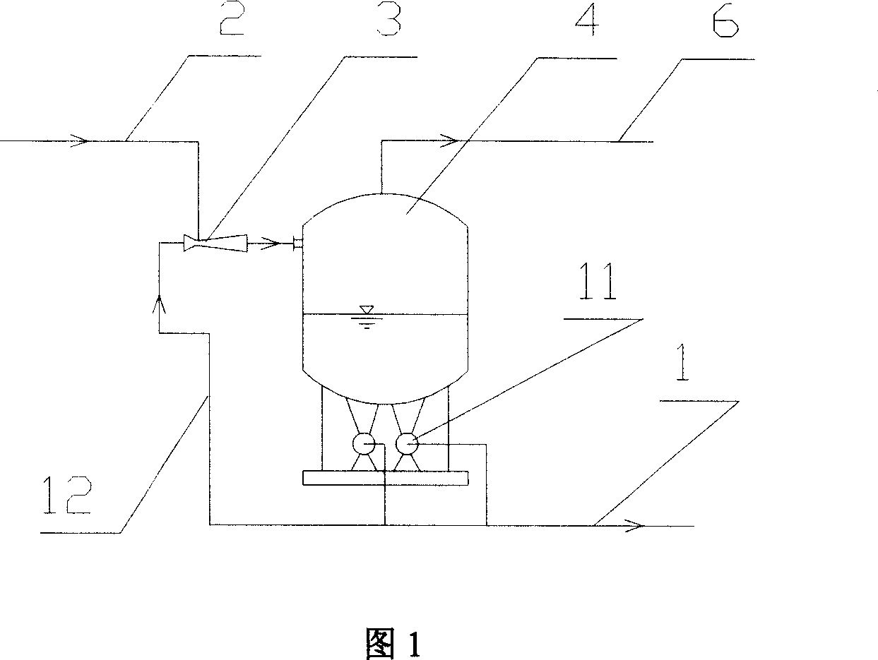
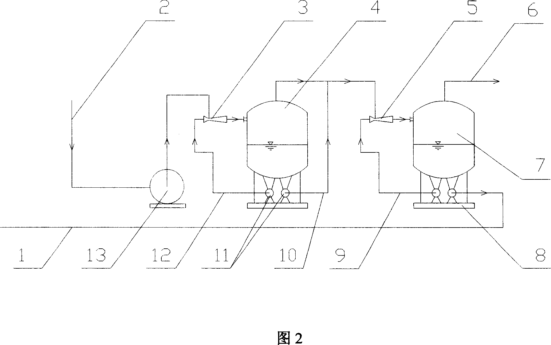
[0010] Referring to Fig. 1 and Fig. 2, the present invention provides a exhaust steam recovery system, comprising a first closed recovery tank 4, the first closed recovery tank is provided with a steam inlet pipe and an exhaust pipe, and the steam inlet pipe is provided with a The booster conveying device 3 for steam inlet boosting, the steam inlet pipe of the booster conveying device is connected with the exhaust steam pipeline 2 .

[0011] The front of the first closed recovery tank can be provided with a steam extraction device 13, and the steam inlet nozzle of the steam inlet pressurized conveying device of the first closed recovery tank is connected with the exhaust steam pipeline through the steam extraction device, Its connection mode is that the steam inlet pipe of the steam extraction device is connected with the exhaust steam pipeline, and the steam exhaust pipe is connected with the steam inlet pressurization conveying device of the first closed recovery tank (referr...


PUM


Abstract

A recovery system of dead steam is prepared as setting steam intake pipe and steam exhaust pipe on the first closed recovery tank, setting pressurization conveying unit for pressurizing inlet steam on steam intake pipe of the first closed recovery tank, connecting steam intake pipe of pressurization conveying unit to dead steam pipe, setting steam sucking unit and the second recovery tank separately before or behind the first closed recovery tank in order to carry out multistage pressurization.

Description

technical field [0001] The invention relates to a exhaust steam recovery system, which can be used for recovery and utilization of exhaust steam of various steam equipment, especially exhaust steam recovery and utilization of steam turbines. Background technique [0002] The exhaust steam of the existing steam turbine is processed through the cooling tower. The steam (exhaust steam) pipe at the end of the steam turbine is directly connected to the condenser. The condenser is a steam-water heat exchanger. Natural cooling water enters the condenser to absorb heat and is The air that is sent to the cooling tower and rises by convection heat transfers heat with the falling cooling water. The exhaust steam in the condenser shrinks sharply from a volume ratio of about 1700:1, forming a vacuum at the end of the steam turbine, thereby increasing the pressure difference between the front and back of the steam turbine and increasing the power generation. The disadvantage of this tech...

Claims


Application Information

Patent Timeline
Patent Type & Authority Applications(China)
IPC IPC(8): F01K19/02
Inventor 李树生
Owner 李树生
Why Eureka
Try Eureka