Supercharge Your Innovation With Domain-Expert AI Agents!

Non-contact type vehicle brake control method and device

A vehicle braking and non-contact technology, which is applied in vehicle components, electric braking systems, electric vehicles, etc., can solve problems such as lack of development, and achieve the effects of improving reliability, long service life, and reducing noise

Inactive Publication Date: 2007-05-16
范双
View PDF0 Cites 5 Cited by
  • Summary
  • Abstract
  • Description
  • Claims
  • Application Information

AI Technical Summary

Problems solved by technology

At present, there is only a single electric motor braking in the world, and the technology of energy recovery by adopting the braking part has not yet been developed.

Method used


Image

  • Non-contact type vehicle brake control method and device

Examples


Embodiment Construction

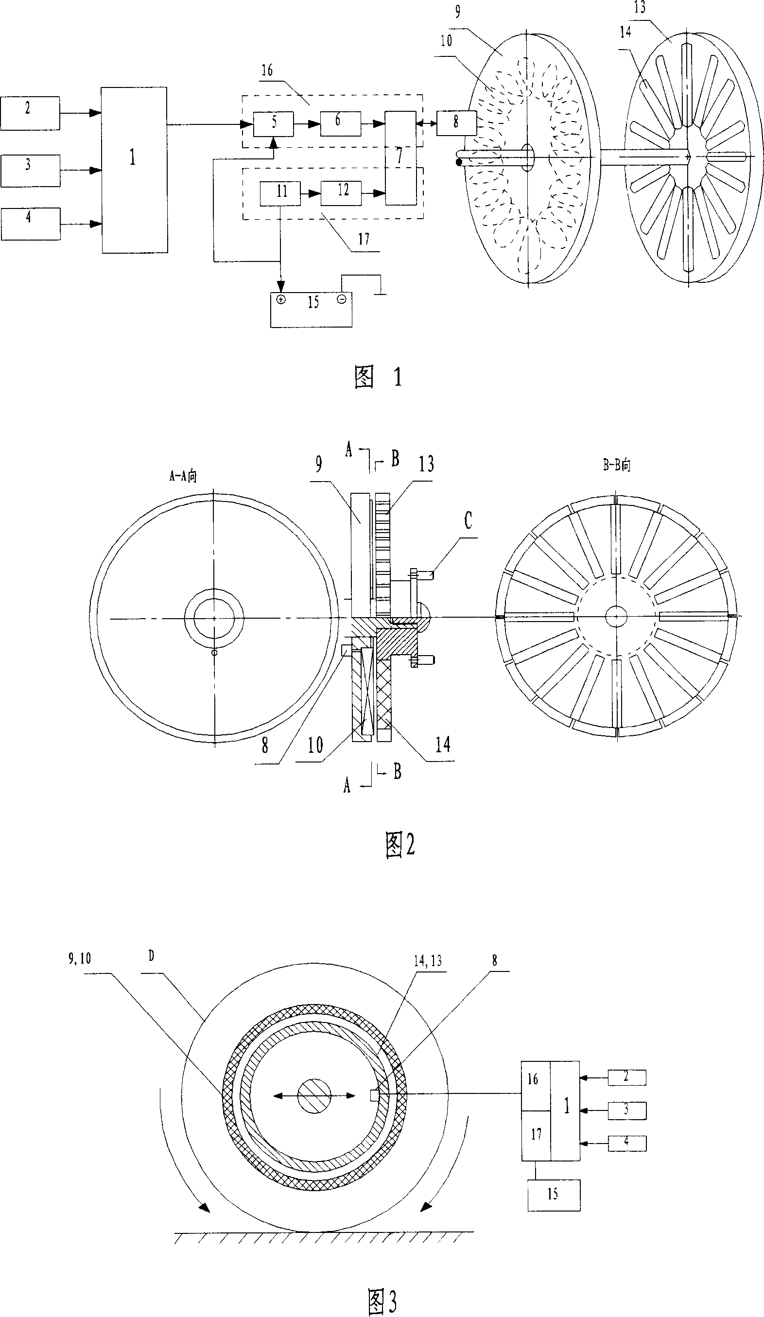
[0018] The specific content and working process of the present invention will be further described below in conjunction with the embodiments shown in the accompanying drawings.

[0019] 1. The control system (ECU) 1 is installed with the software "controlling braking force output program".

[0020] An important part of the "control braking force output program" is the braking force parameter database, which is the result of summarizing and optimizing a large number of experimental data. In the database, each piece of data corresponds to the analog data transmitted by the brake pedal sensor 2 respectively. The analog data of the sensor is a linear signal that changes from small to large. After linear arrangement and software filtering, the signal is input into the control system (ECU) 1 and stored in the memory. The data in the memory changes dynamically and is constantly refreshed. The control system (ECU) 1 searches for the best precision to control the output of the brakin...


PUM


Abstract

The invention relates to a non-touch vehicle brake control method and relative device, wherein it can reduce noise and improve reliability. Its control method comprises based on the input of brake pedal sensor, controlling the output of brake power on the wheel; based on the inputs of shift signal and idle position, controlling the energy recycle condition of sliding wheel. The invention is formed by control system (ECU), brake pedal sensor, power source, fixed disc, and rotation disc. The control brake output module and energy control recycle module are connected to the power source, and via wires are connected to the winding of fixed disc; the fixed disc is mounted on the support relative to the rotation disc; the rotation disc is connected to the wheel and rotates together.

Description

technical field [0001] The invention belongs to the field of vehicle electronic automatic control, in particular to a non-contact vehicle braking control method and device. Background technique [0002] Vehicle electronic automatic control braking is a new technology that has just emerged, and it is the development direction of future vehicle design and manufacture. At present, there is only a single electric motor braking in the world, and the technology of energy recovery by adopting the braking part has not yet been developed. Contents of the invention [0003] The object of the present invention is to provide a non-contact vehicle braking control method and device installed on a vehicle. [0004] The technical scheme of the present invention will be described below in conjunction with the accompanying drawings. The invention is based on the principle of electromagnetic effect that produces repulsive force by changing the size of the passing current by moving the wire...

Claims


Application Information

Patent Timeline
Patent Type & Authority Applications(China)
IPC IPC(8): B60L7/10
Inventor 范双范巨新
Owner 范双
Features
  • R&D
  • Intellectual Property
  • Life Sciences
  • Materials
  • Tech Scout
  • Unparalleled Data Quality
  • Higher Quality Content
  • 60% Fewer Hallucinations
Learn More