
Translational device for crane slings

A technology of translation device and crane, which is applied in the direction of transportation and packaging, load hanging components, etc., which can solve the problems of high fuel consumption, poor operator comfort, and heavy lifting weight

Inactive Publication Date: 2007-05-16
SHANGHAI PORT MACHINERY HEAVY IND
View PDF0 Cites 8 Cited by
  • Summary
  • Abstract
  • Description
  • Claims
  • Application Information

AI Technical Summary

Problems solved by technology

[0006] Aiming at the disadvantages existing in the prior art, such as long loading and unloading time, heavy lifting weight, complex installation and arrangement, difficult maintenance, large loss of traveling mechanism, difficult selection of lifting mechanism, large oil consumption, and poor operator comfort, the invention provides A spreader translation device in the direction of the crane. The device is simple in structure and easy to operate. It can not only realize the rapid translation of the spreader in the direction of the crane cart, but also realize the rotation, left-right tilt, front-back tilt and other actions of the spreader.

Method used

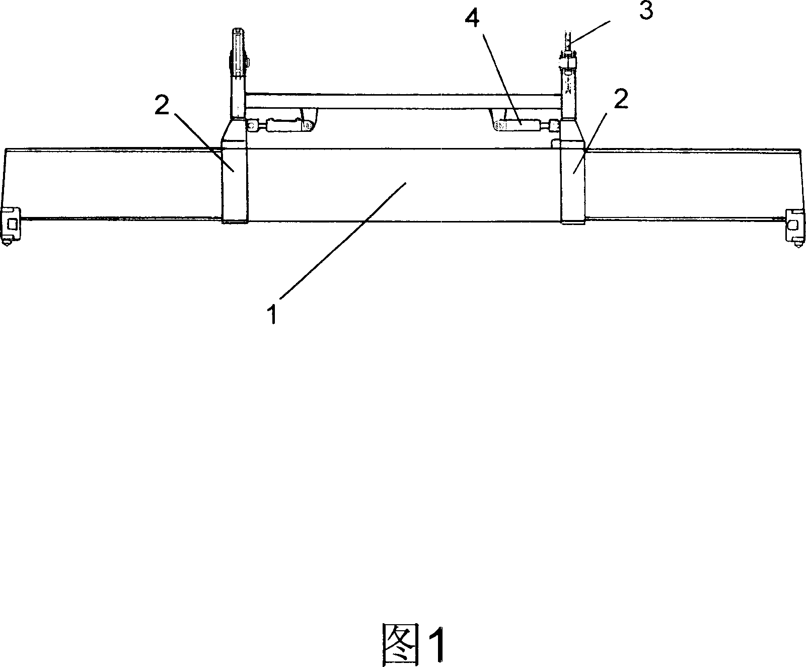

Image

  • Translational device for crane slings
  • Translational device for crane slings
  • Translational device for crane slings

Examples


Embodiment 1

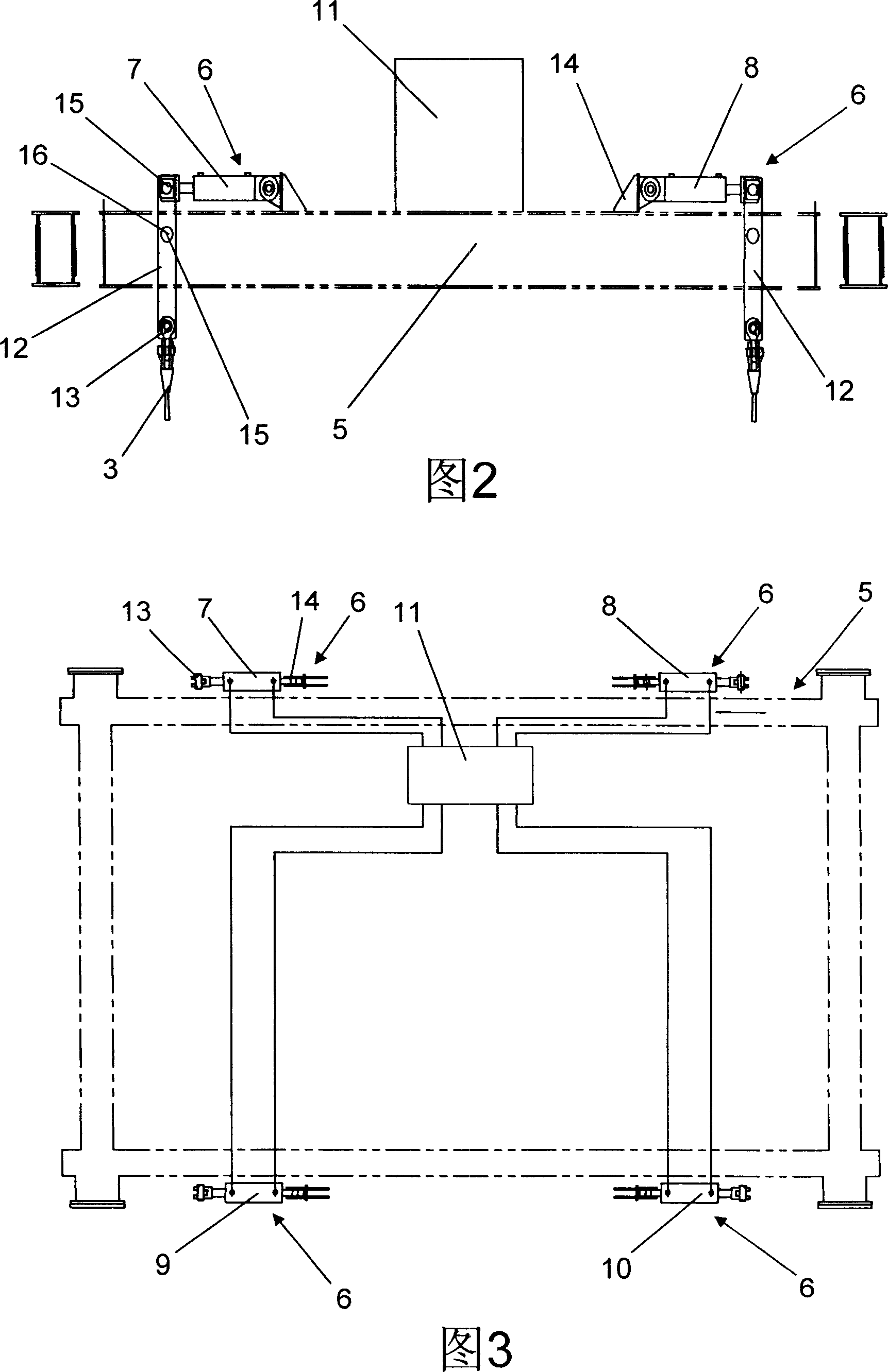
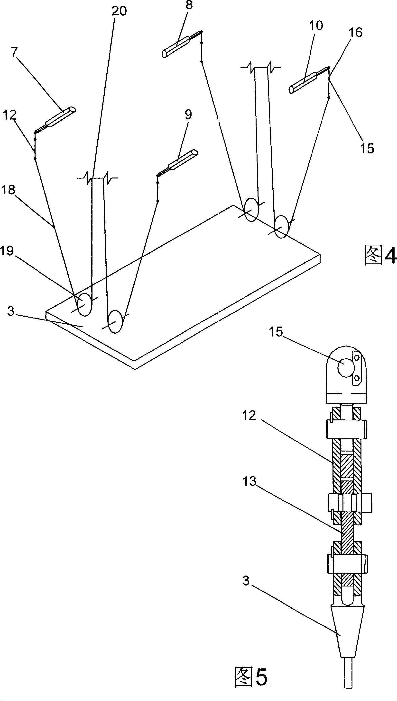
[0024] As shown in Figure 2 and Figure 3, the translation device includes a trolley 5 and a driving device 6, the driving device is arranged on the trolley 5, and the driving device 6 further includes: hydraulic cylinders 7, 8, 9, 10, hydraulic pump station 11. Lever 12 and wire rope winding system 13; there are four sets of hydraulic cylinders 7, 8, 9, and 10, which are located on both sides of the trolley 5 in pairs, and the two hydraulic cylinders 7, 8 or 9, 10 on the same side are spaced apart For a certain distance, one end support 14 of each hydraulic cylinder is fixed on the trolley 5 by welding, and the other end is provided with a lever 12 and connected to the upper end of the lever through a pin 15; the fulcrum 16 of the lever is fixed on the trolley 5 through the pin 15 The lower end of the lever 12 has a wire rope winding system 13 and is connected with the upper frame 3 of the spreader; the hydraulic pump station 11 is in the middle of four groups of hydraulic cyli...

Embodiment 2

[0027] On the original basis of Embodiment 2, a push rod device is used to replace the hydraulic cylinder and the pump station.

[0028] Please refer to Fig. 2, shown in Fig. 3, this translation device comprises trolley 5 and driving device 6, and driving device is arranged on trolley 5, and driving device 6 further comprises: push rod, lever 12 and wire rope winding system 13; Push rod (the push rod is similar to a common long rod, not shown in the figure) there are four groups, which are respectively located on both sides of the trolley 5 in twos, with a distance between the push rods on the same side, and one end of each push rod supports The seat 14 is fixed on the trolley 5 by welding, the other end is provided with a lever 12 and connected to the upper end of the lever through the pin 15; the fulcrum 16 of the lever is fixed on the side of the trolley 5 through the pin 15, and the lower end of the lever 12 is wound with a wire rope System 13 is also connected with hanger...


PUM


Abstract

The invention relates to a translator of crane, wherein it comprises a carrier cart and a driver; the driver is on the cart; the driver comprises hydraulic cylinder, hydraulic pump, lever, and steel wire coiling system; there are four groups of hydraulic cylinders while each two are mounted at one side of cart; one end of each hydraulic cylinder via base is fixed on the cart, while another end is connected to the upper end of lever; the support point of lever is fixed on the of cart; the lower end of lever has steel wire coiling system to connect the lifter upper frame; the hydraulic pump is between four hydraulic cylinder groups and connected to each cylinder; the steel wire coiling system comprises steel wire, block, and steel wire roller. The invention has simple structure, while it can translate the lifter on the large cart of crane and rotate lifter, etc.

Description

technical field [0001] The invention relates to an auxiliary tool for container loading and unloading equipment, and more specifically, relates to a crane spreader translation device. Background technique [0002] The existing container loading and unloading equipment used in the container yard mainly includes: container tire type gantry crane (RTG) and rail type gantry crane. Because in the container loading and unloading operation, it is impossible for the container transport truck to stop just parallel to the spreader of the crane, that is, the center line of the container on the container transport truck and the center line of the spreader of the crane produce a certain deflection angle. At this time, it is necessary to use The spreader slewing device installed on the crane equipment rotates at a certain angle, so that the centerline of the spreader coincides with the centerline of the container, and the operation can be continued after adjustment. The spreader slewing ...

Claims


Application Information

Patent Timeline
IPC IPC(8): B66C13/04
Inventor 李国辉王晓亮
Owner SHANGHAI PORT MACHINERY HEAVY IND
Learn More