Generation power device by using road deceleration strip

A technology of power unit and speed reduction belt, applied in the direction of engine, machine/engine, mechanical equipment, etc., can solve the problems of low operation efficiency, complex transmission structure, poor reliability, etc., and achieve the effect of reliable operation, wide application range and simple structure

Inactive Publication Date: 2007-05-16
赵虹
View PDF0 Cites 18 Cited by
  • Summary
  • Abstract
  • Description
  • Claims
  • Application Information

AI Technical Summary

Problems solved by technology

A few days ago, the applicant had researched and designed a mechanical transmission road deceleration belt power devic

Method used


Image

  • Generation power device by using road deceleration strip

Examples


Embodiment Construction

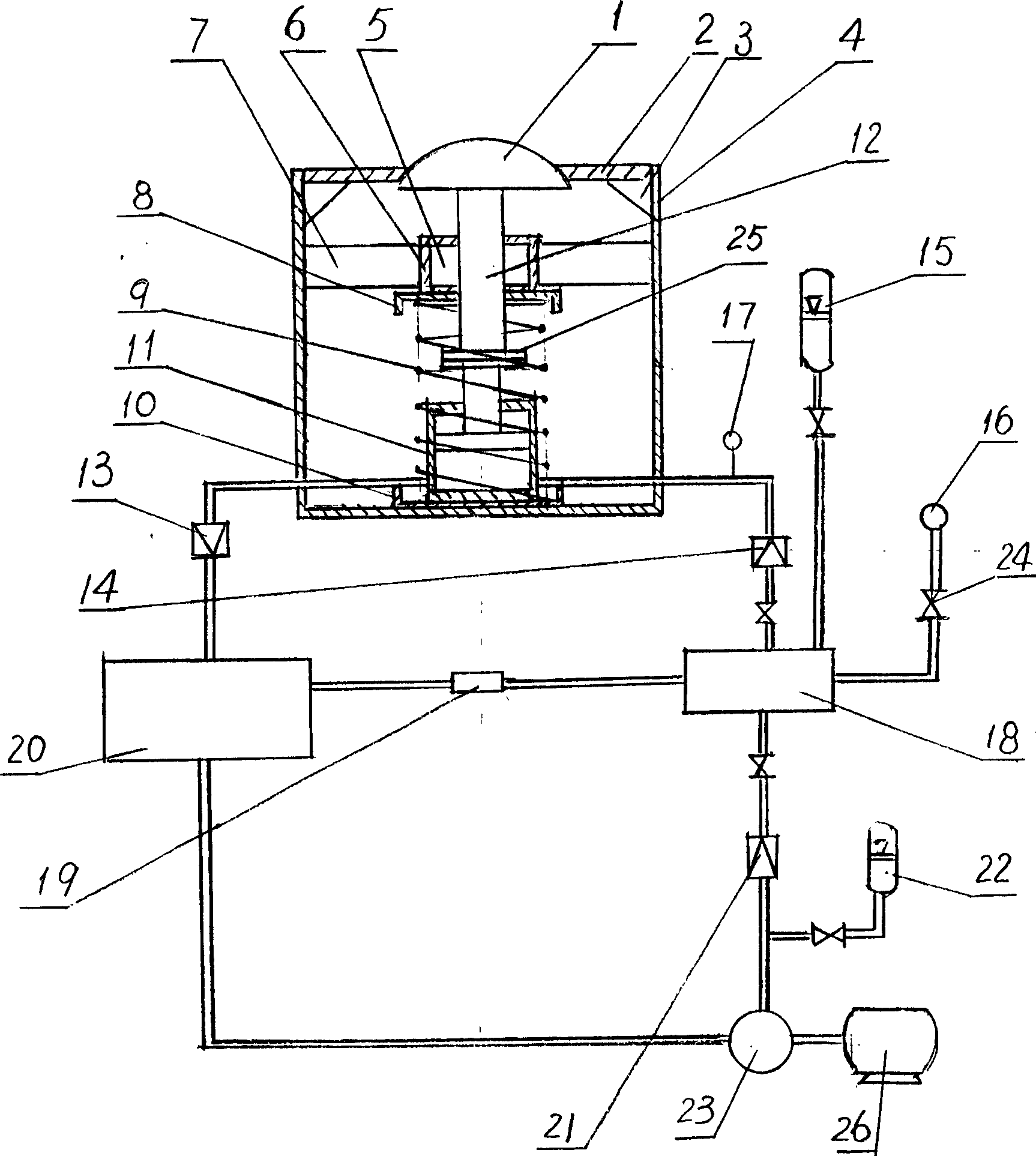
[0009] Embodiments of the present invention will be described in detail below in conjunction with the accompanying drawings. The road deceleration belt generating power device includes a box body 4 and a generator 26. A lower supporting plate 10 is installed on the inner bottom surface of the box body 4. The hydraulic cylinder 11 is fixed upright on the lower supporting plate 10. The coupling 25 is arranged on the hydraulic cylinder. Between the end of the cylinder rod 11 and the lower end of the pressure rod 12, the cylinder rod and the pressure rod 12 are connected into one body, the upper end of the pressure rod 12 is fixed with the pressure plate 1, the guide sleeve 5 is fitted on the pressure rod 12, and the positioning The sleeve 6 is fitted outside the guide sleeve 5 to accommodate the guide sleeve 5, the positioning plate 7 and the positioning sleeve 6 are assembled into one body, the positioning plate 7 is fixed on the inner wall surface of the box body 4; the upper su...


PUM


Abstract

The road deceleration strip generator device has bottom support and hydraulic cylinder at the bottom of the inside of the case, a shaft connector linking a compression bar that has a compression plate and an upper support plate with a cylinder bar, the compression bar cased by a guiding sheathing with an outside locating sleeve that is fastened on the inner wall of the case by the locating plate. A compression spring that's up and bottom ends contact with the upper and bottom support respectively, cases around a hydraulic cylinder and a compression bar. Inside the upper end of the case fastens a support plate and a fastening plate that fits with the compression plate in restraint. The inlet and outlet of the hydraulic cylinder connects with a hydraulic system made of an oil tank, a hydraulic tank, a hydraulic motor and a accumulating with the hydraulic motor connected with the generator. This equipment is reasonable in design, simple in structure, energy saving, environment friendly, low in running cost, efficient and reliable in operation.

Description

technical field [0001] The invention belongs to power energy equipment, and mainly relates to an energy device that relies on the gravity of a running automobile to press down to generate power and generate electricity. Background technique [0002] In order to reduce and avoid the occurrence of traffic accidents caused by excessive speed during driving, at present, most of the bustling roads with large traffic volume in the city, intersections and tens of meters before expressway toll stations are installed horizontally on the road. The speed bumps (also known as speed bumps, etc.) made of elastic materials with certain elasticity, because the speed bumps are higher than the road surface, so when the vehicle drives here, it must slow down and pass, and the purpose of setting the speed bump is achieved. However, when the vehicle passes through the speed bump, the potential energy power generated by the vehicle's gravity is lost and wasted in vain, without any beneficial effe...

Claims


Application Information

Patent Timeline
IPC IPC(8): F03G3/00H02K7/18
Inventor 赵虹
Owner 赵虹
Why Eureka
Try Eureka