Testing apparatus for high temperature, superconducting, magnetic suspension and dynamic performance and testing method with the same

A high-temperature superconducting and testing device technology, which is applied in the direction of measuring devices, motor generator testing, and electric/magnetic devices to transmit sensing components, can solve problems such as the inability to simulate the operation of high-temperature superconducting maglev vehicles, and achieve convenient and automatic Effects of control and treatment

Inactive Publication Date: 2007-05-16
SOUTHWEST JIAOTONG UNIV
View PDF2 Cites 39 Cited by
  • Summary
  • Abstract
  • Description
  • Claims
  • Application Information

AI Technical Summary

Problems solved by technology

Therefore, the existing test equipment cannot simulate the real operation of the HTS maglev vehicle

Method used


Image

  • Testing apparatus for high temperature, superconducting, magnetic suspension and dynamic performance and testing method with the same

Examples


Embodiment 1

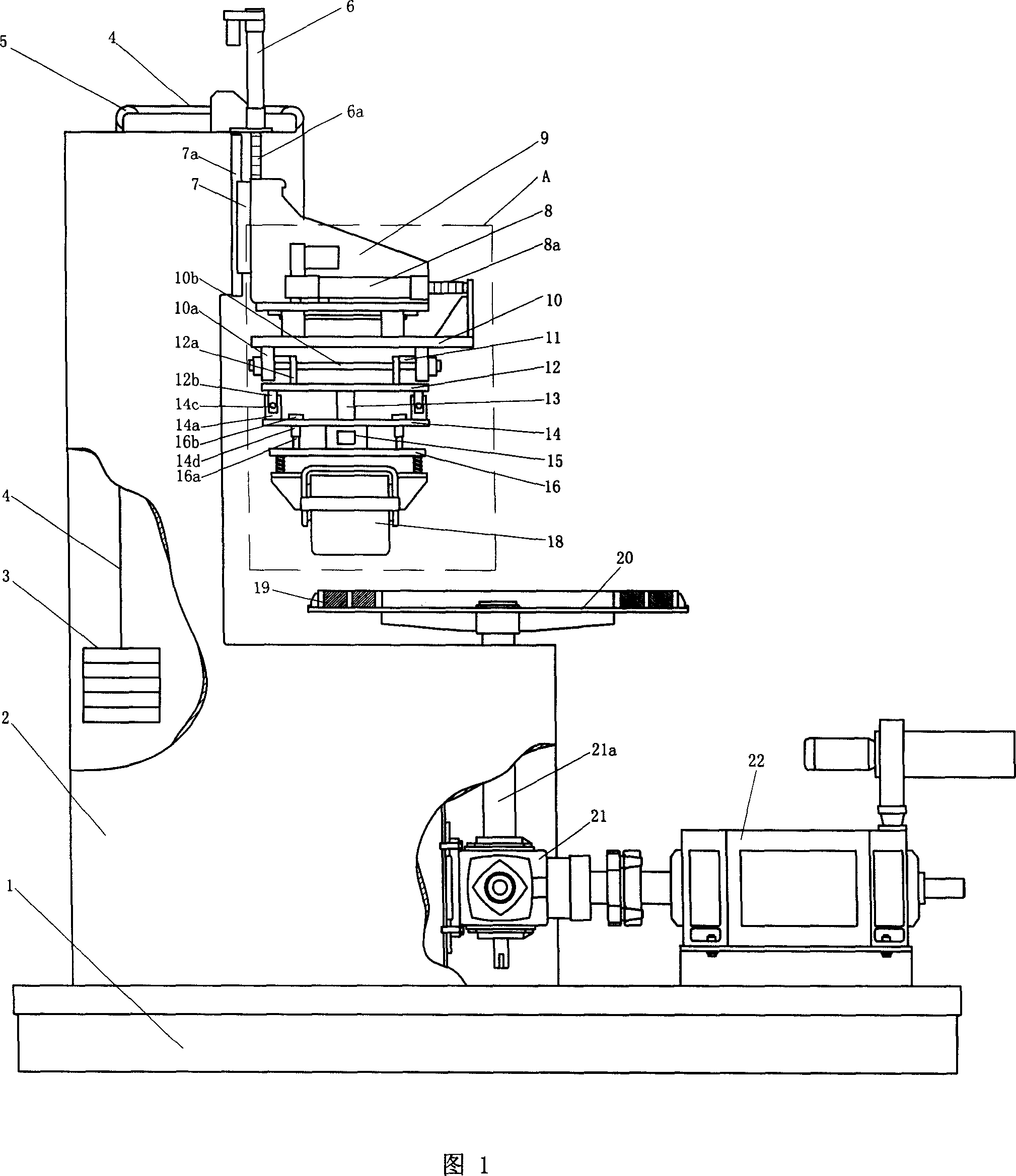
[0087] Fig. 1 shows a kind of high-temperature superconducting magnetic levitation dynamic performance testing device of the present invention, and it consists of:

[0088] a, the anti-seismic base 1 is equipped with a stainless steel L-shaped frame 2 and a horizontal stainless steel disc 20 driven by a motor 22, and a circle of high-temperature ultra- Guide car with magnetic track 19.

[0089] b. A vertical loading electric cylinder 6 is installed on the top of the L-shaped frame 2, and the screw rod 6a below the vertical loading electric cylinder 6 is connected to the support frame 9 of the three-dimensional force measuring device A, and the back of the support frame 9 slides vertically Installed on the inner side of the upper part of the L-shaped frame 2; the support frame 9 is fixed with a laterally loaded electric cylinder 8, and the screw rod 8a protruding forward of the electric cylinder 8 is connected with the side plate of the upper slide plate 10, and the upper slide...

Embodiment 2

[0105] The composition of this example is basically the same as that of Embodiment 1, and the difference is only: the output shaft 21a of the transmission mechanism 21, which is connected to the center of the vertical stainless steel disc 20, and the annular high-temperature superconducting vehicle magnetic rail 19 is fixed Above the edge of the stainless steel disc 20, the arrangement of multiple high-temperature superconducting blocks in the Dewar vessel 18 is arc-shaped, and the center of the arc is the same as the center of the high-temperature superconducting vehicle magnetic rail 19, that is, the stainless steel circle. The center of the disc coincides.

Embodiment 3

[0107] The composition of this example is basically the same as that of Embodiment Two, except that the vertical stainless steel disk 20 is two coaxially connected; Above the edge, so that two sets of high-temperature superconducting blocks side by side can be tested, and the magnetic levitation performance under the condition of relative motion with a pair of high-temperature superconducting vehicle magnetic rails 19 can be more realistically simulated on both sides of the high-temperature superconducting maglev train The test data of the superconducting bulk material and the state running above the two rails are more practical.


PUM


Abstract

This invention relates to high temperature super conductive magnetic float dynamic test device, wherein, the bottom socket motor drives stainless steel disc and its top ring high temperature superconductive float cargo magnetic rotation; the bottom L shape shell top has been loaded with cylinder to drive down supportive rack for sliding along rack; the supportive rack is loaded with motor cylinder along supportive rack down level movement; upper and middle slide boards are fixed with sensor test level guide force; middle board and its down slide board can slide for vertical sliding.

Description

technical field [0001] The invention relates to a high-temperature superconducting magnetic levitation dynamic performance testing device. Background technique [0002] High-temperature superconducting maglev trains are one of the important applications of high-temperature superconducting bulk materials in the field of maglev technology. When designing and developing high-temperature superconducting maglev trains, it is necessary to conduct detailed research and testing on various levitation properties of high-temperature superconducting bulk materials. However, due to the influence of experimental conditions and testing techniques, the current testing devices can only study the suspension force or guiding force of high-temperature superconducting bulk materials under static or quasi-static conditions. It is impossible to test the suspension force, guiding force, longitudinal force, suspension force stiffness, etc. of the block under dynamic conditions, and it is impossible ...

Claims


Application Information

Patent Timeline
Patent Type & Authority Applications(China)
IPC IPC(8): G01L1/00G01L5/00G01D5/12G01D5/244G01R31/34G01D21/00G01N27/00
Inventor 王家素曾佑文邓昌延王素玉张龙财邓自刚郑珺曾刚黄永刚刘明贤芦逸云许志沛
Owner SOUTHWEST JIAOTONG UNIV
Why Eureka
Try Eureka