
Mixer nozzle and method for mixing two or more fluids and process for manufacturing isocyanates

A technology of nozzles and fluids, applied in the preparation of organic compounds, fluid mixers, chemical instruments and methods, etc., which can solve the problems of unattractive manufacturing costs

Inactive Publication Date: 2007-05-16
HUNTSMAN INT LLC
View PDF1 Cites 6 Cited by
  • Summary
  • Abstract
  • Description
  • Claims
  • Application Information

AI Technical Summary

Problems solved by technology

[0010] However, such mixing devices have a number of disadvantages, in particular the formation of possible solid deposits (eg scaling) on ​​the tips of the projections, which cannot be cleaned without shutting down the device
At the same time, the mixing device requires a central body with high precision, i.e. an additional part to be manufactured, which makes the manufacturing costs unattractive

Method used


Image

  • Mixer nozzle and method for mixing two or more fluids and process for manufacturing isocyanates
  • Mixer nozzle and method for mixing two or more fluids and process for manufacturing isocyanates
  • Mixer nozzle and method for mixing two or more fluids and process for manufacturing isocyanates

Examples


Embodiment Construction

[0021] Other purposes, features and beneficial effects will be more apparent after referring to the following description.

[0022] The invention is based on the use of rectangular nozzles referred to hereinafter as slot nozzles. The special geometry allows for fine flows while at the same time avoiding central protruding elements.

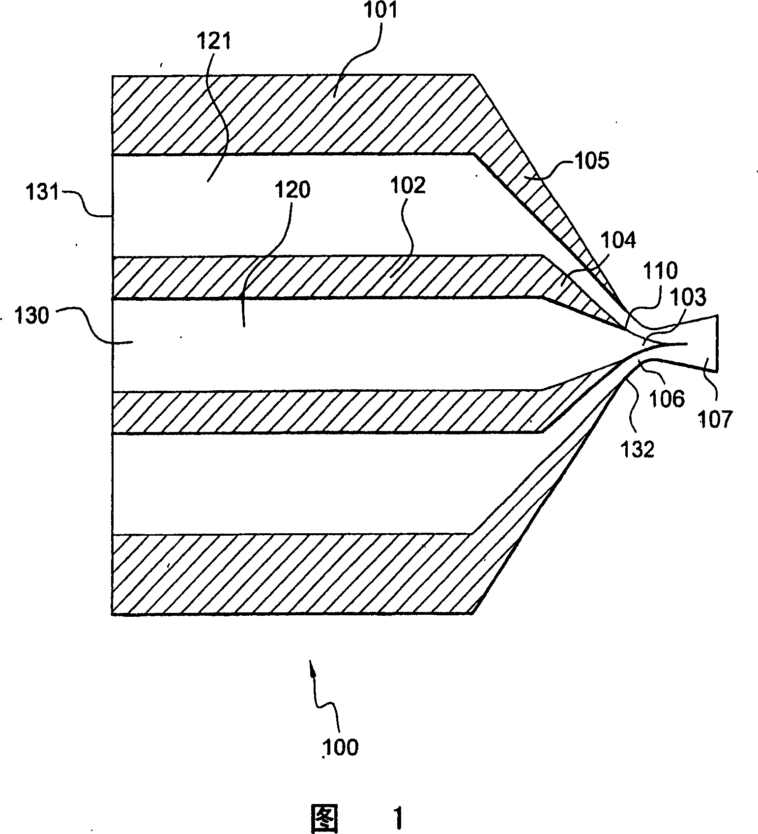
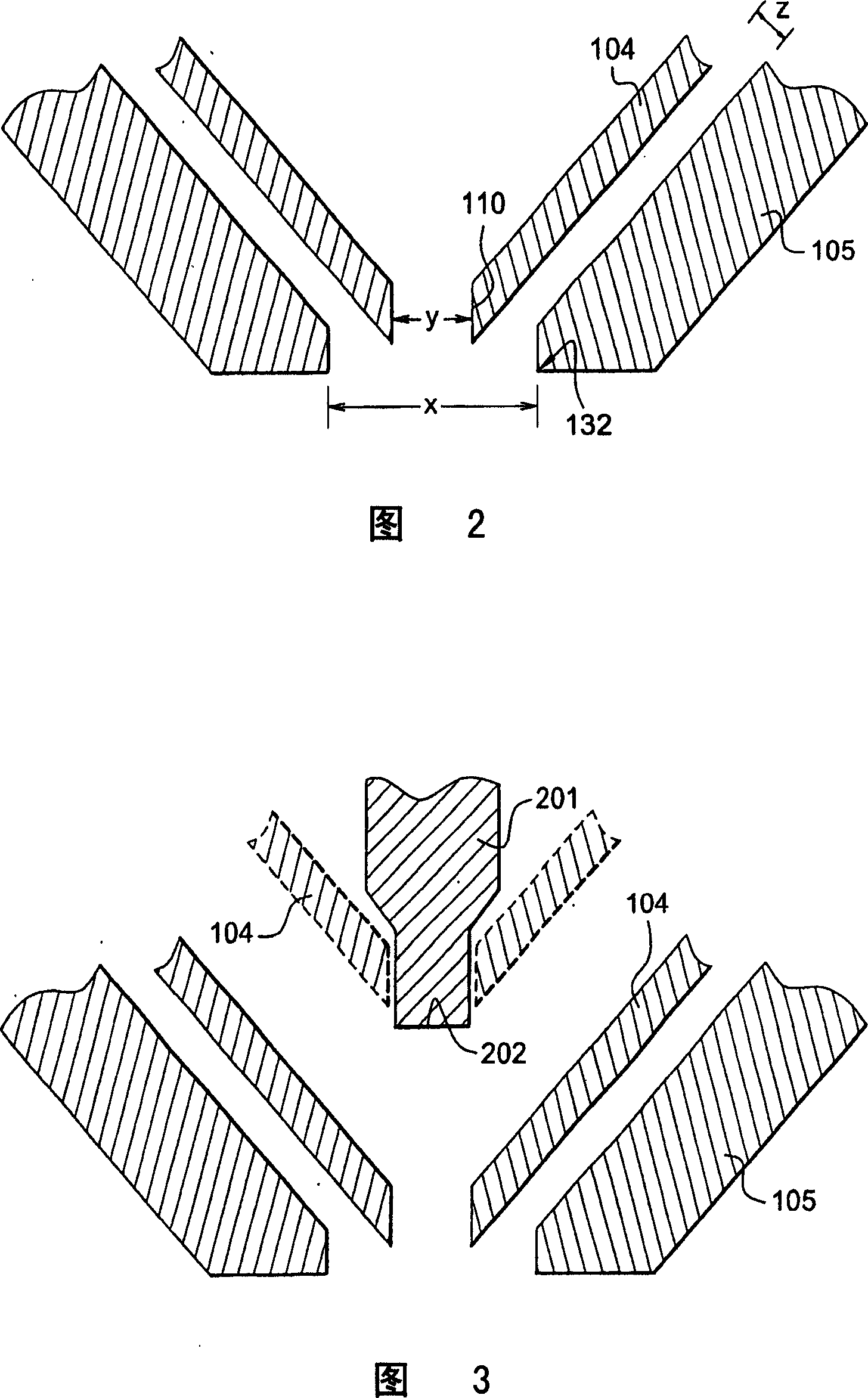
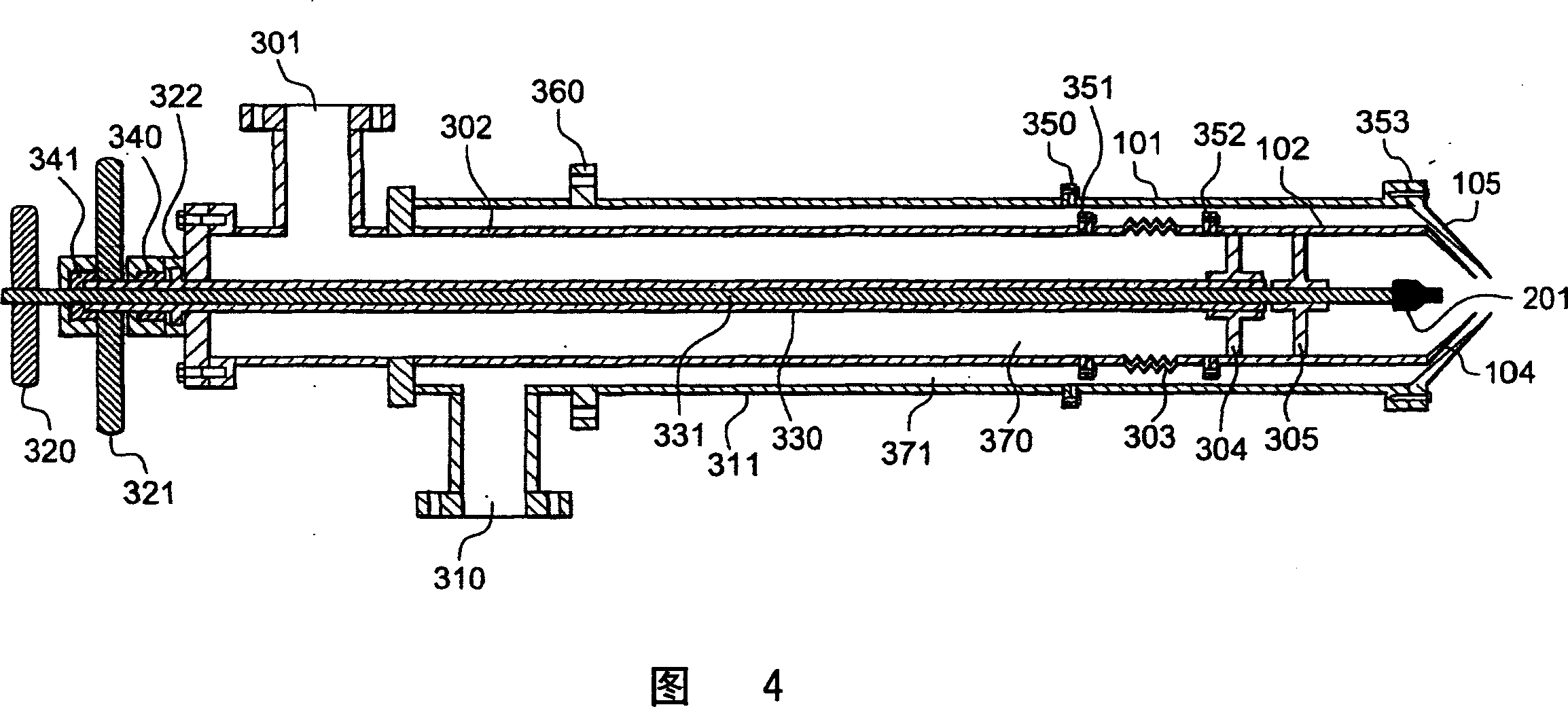
[0023] As shown in FIG. 1, there is shown a coaxial impinging jet mixer nozzle assembly 100 for mixing two fluids. The coaxial impinging jet mixer nozzle assembly 100 includes an inner flow conduit 102 and an inner flow conduit nozzle tip 104 disposed coaxially inside an outer flow conduit 101 and an outer flow conduit nozzle tip 105 . Flow chamber 120 is defined as a rectangular space inside inner flow conduit 102 and inner flow conduit nozzle tip 104 . The flow chamber 120 has two ends, a supply end 130 and a discharge end 110 . The discharge end 110 of the flow chamber 120 is formed by the discharge end of the inner flow conduit nozzle tip 1...


PUM


Abstract

A mixing apparatus includes coaxial first and second nozzles (104,105) that taper toward respective discharage ends (110,132) and that have rectangular cross sections. The apparatus may be used to mix fluids, for example to mix phosgene with amines to produce and isocyanates.

Description

technical field [0001] The present invention relates to a novel apparatus for mixing fluids, especially amines, and phosgene, and to a process for mixing amines and phosgene to prepare carbamoyl chlorides and isocyanates. Background technique [0002] Numerous documents disclose nozzles for mixing fluids, especially reactive fluids. Specifically, for example in phosgenation reactions, rapid mixing is a key parameter. Consequently, many designs of such nozzles have been proposed, the vast majority of which have coaxial jets that may or may not impinge. [0003] WO-A-2004004878 discloses such a jet mixer nozzle for carrying out a phosgenation reaction comprising: [0004] (a) a first nozzle comprising a first flow conduit having a converging, tapered first nozzle tip having a first discharge opening; [0005] (b) a second nozzle comprising a second flow conduit having a converging, tapered second nozzle tip having a second discharge opening, wherein the second nozzle is coa...

Claims


Application Information

Patent Timeline
Patent Type & Authority Applications(China)
IPC IPC(8): B01F5/04
CPCB01F5/20B01F3/08C07C263/10B01F2215/0036B01F5/046B01F5/0256B01F23/40B01F25/23B01F25/31324B01F25/72B01F2101/2204C07C265/10C07C265/12
Inventor J·E·卢瑟R·S·古坦塔格J·Y·斯图阿特
Owner HUNTSMAN INT LLC
Learn More