
Anti-scatter-grid

An anti-scatter grid, X-ray technology, applied in radiation/particle processing, using diaphragm/collimator, nuclear engineering, etc., can solve the problems of high cost, small pixel size, difficult to make metal foil, etc.

Inactive Publication Date: 2007-05-16
KONINKLIJKE PHILIPS ELECTRONICS NV
View PDF0 Cites 13 Cited by
  • Summary
  • Abstract
  • Description
  • Claims
  • Application Information

AI Technical Summary

Problems solved by technology

2D arrays are supposed to give higher efficiencies, but are difficult to fabricate from metal foils
Several methods have been proposed for this purpose, but to date these have suffered from poor quality or stability, high complexity, high cost, or inappropriateness for small pixel sizes

Method used


Image

  • Anti-scatter-grid
  • Anti-scatter-grid
  • Anti-scatter-grid

Examples


Embodiment Construction

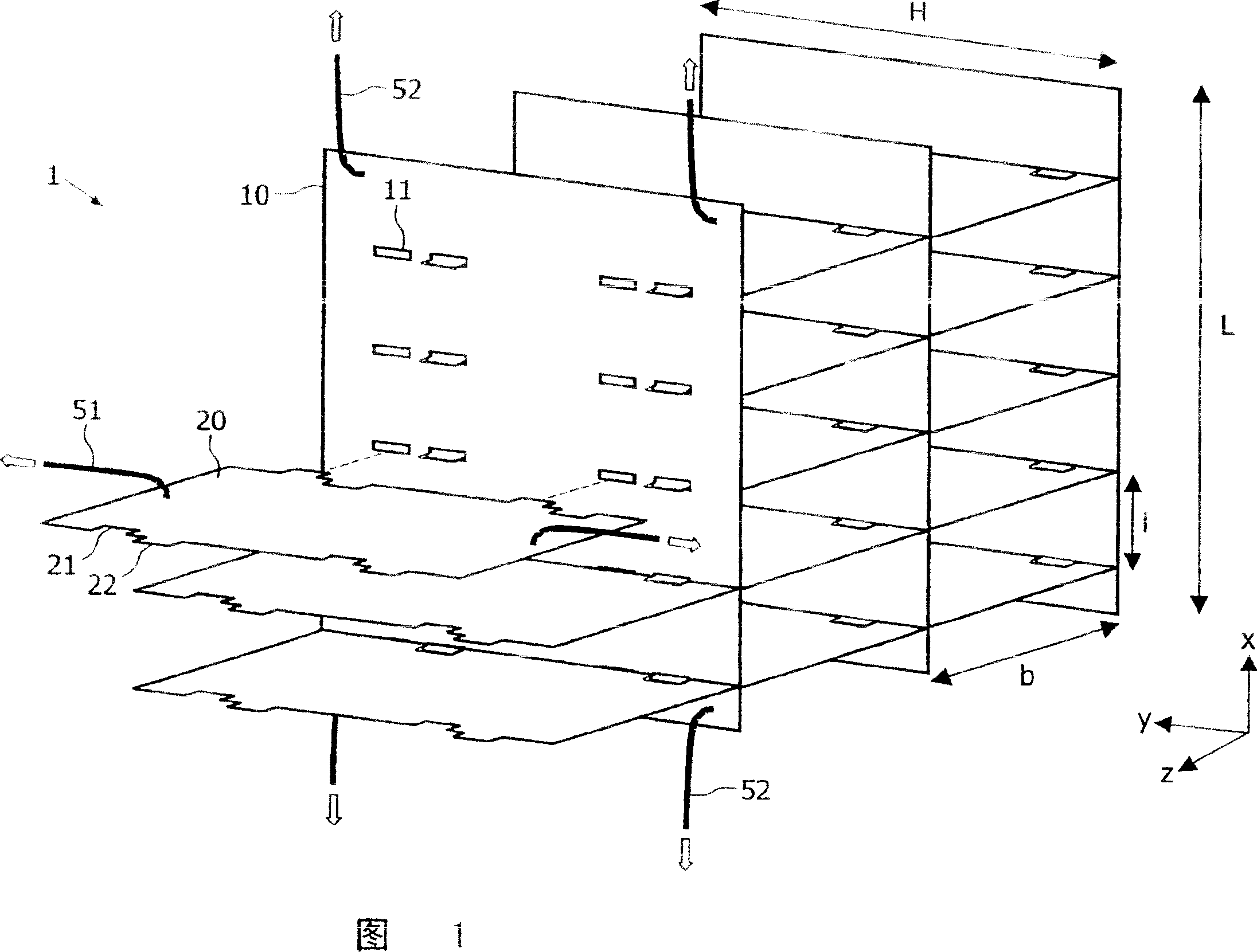
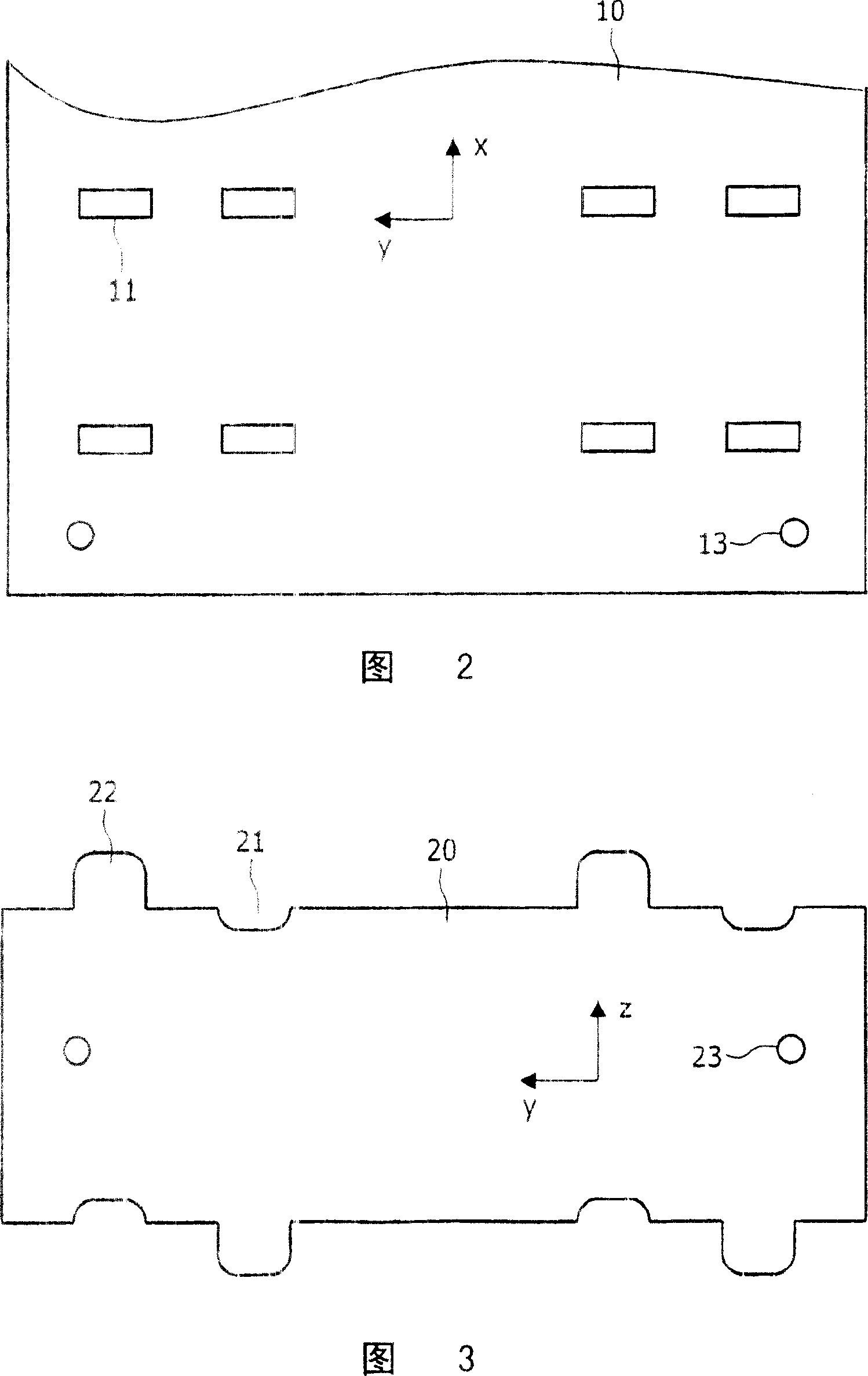
[0036] Figure 1 shows a part of an anti-scatter-grid 1 in a partially assembled state. The grid is said to be "two-dimensional" because it comprises walls 10, 20 running in two perpendicular directions x, z. These walls form a rectangular grid or matrix of channels through which radiation (eg X-rays) can pass in the y-direction to components placed behind the grid (eg detectors, not shown). Rays that are not aligned with the channels of the anti-scatter grid 1 will be absorbed when they hit the grid walls. The material of the walls 10, 20 is usually a metal with a high absorption coefficient for the radiation to be filtered, for example a heavy metal like tungsten or molybdenum in the case of X-rays. Furthermore, it should be noted that this figure represents only a small portion of an anti-scatter grid, which typically includes hundreds or thousands of channels. The height H of the anti-scatter grid corresponds to the length that the rays must pass through the grid, usually...


PUM


Abstract

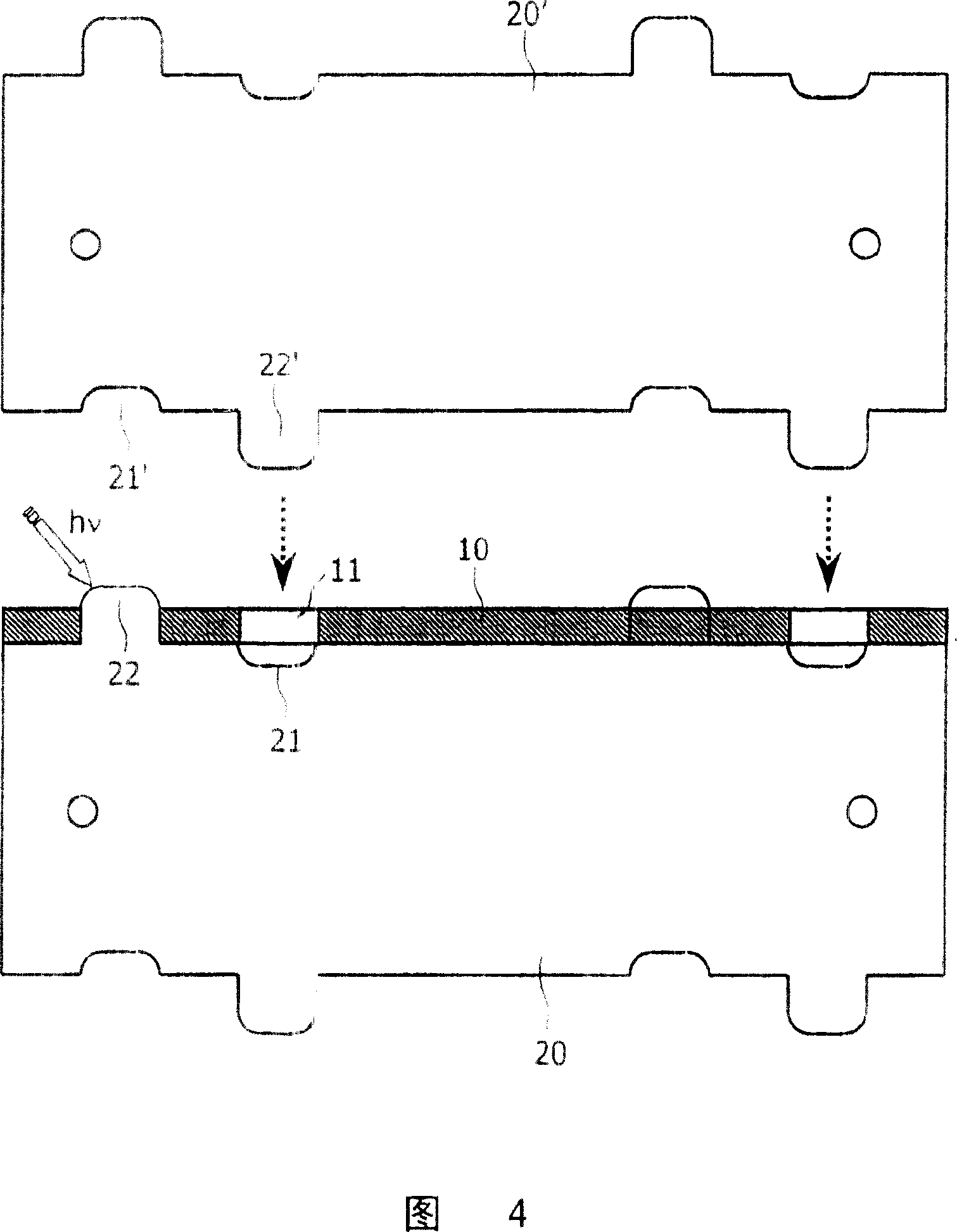
The invention relates to an Anti-Scatter-Grid (1) that consists of carrier walls (10) and, transversal thereto, partition walls (20). Noses (22) of the partition walls (20) are inserted into holes (11) of the carrier walls (10) and fixed thereto by laser welding. The noses (22) preferably project from the backside of the carrier walls in order to facilitate welding and alignment. Moreover, various tools are proposed that assist the accurate assembling of the Anti-Scatter-Grid.

Description

technical field [0001] The invention comprises an anti-scatter-grid and components thereof, a detector and an inspection device having such an anti-scatter-grid, and auxiliary tools for manufacturing such an anti-scatter-grid. Background technique [0002] Scattering of X-rays can seriously degrade the image quality of X-ray detectors. The Anti-Scatter Grid (ASG) transmits X-rays only in a small angular range, thereby limiting a large amount of scattered X-rays. The simplest form of such an anti-scatter grid consists of a one-dimensional sandwich structure of thin heavy metal foils (e.g. tungsten or molybdenum, 0.1 mm thickness, 20 mm height) separated by a low X-ray absorbing material (e.g. air or plastic, 1 mm thickness). array. Two-dimensional arrays are supposed to give higher efficiencies, but are difficult to fabricate from metal foils. Several methods have been proposed for this purpose, but so far these methods have the disadvantage of poor quality or stability, h...

Claims


Application Information

Patent Timeline
Patent Type & Authority Applications(China)
IPC IPC(8): G21K1/02
CPCG21K1/025
Inventor W·埃肯贝克
Owner KONINKLIJKE PHILIPS ELECTRONICS NV
Learn More