Buoyancy scanning type polyphase liquid-level interface detection method and detector therefor

A detection method and a scanning technology, which is applied in the direction of buoy liquid level indicator, liquid level indicator, liquid/fluid solid measurement, etc., can solve the problems of unusable liquid level detection, radiation hazard, sinking to the bottom of the liquid, etc.

Inactive Publication Date: 2007-05-23
DANDONG DONGFANG MEASUREMENT&CONTROL TECHCO
View PDF0 Cites 15 Cited by
  • Summary
  • Abstract
  • Description
  • Claims
  • Application Information

AI Technical Summary

Problems solved by technology

The technical problems existing in the existing float level gauge are: first, it can only be used for single liquid level detection, but cannot be used for the detection of the interface and liquid level of two or more immiscible multiple media; the second is: It is only suitable for detection occasions where the specific gravity (or density) of the measured liquid is constant. When the specific gravity (or density) of the liquid itself changes, the floating height of the float will change accordingly, resulting in a large measurement error. , cannot even detect
For example, for the same liquid level, when the density of the liquid increases, its buoyancy increases, and the floating position of the float will rise; when the density of the liquid decreases, its buoyancy decreases, and the floating height of the float also de

Method used


Image

  • Buoyancy scanning type polyphase liquid-level interface detection method and detector therefor
  • Buoyancy scanning type polyphase liquid-level interface detection method and detector therefor
  • Buoyancy scanning type polyphase liquid-level interface detection method and detector therefor

Examples


Embodiment Construction

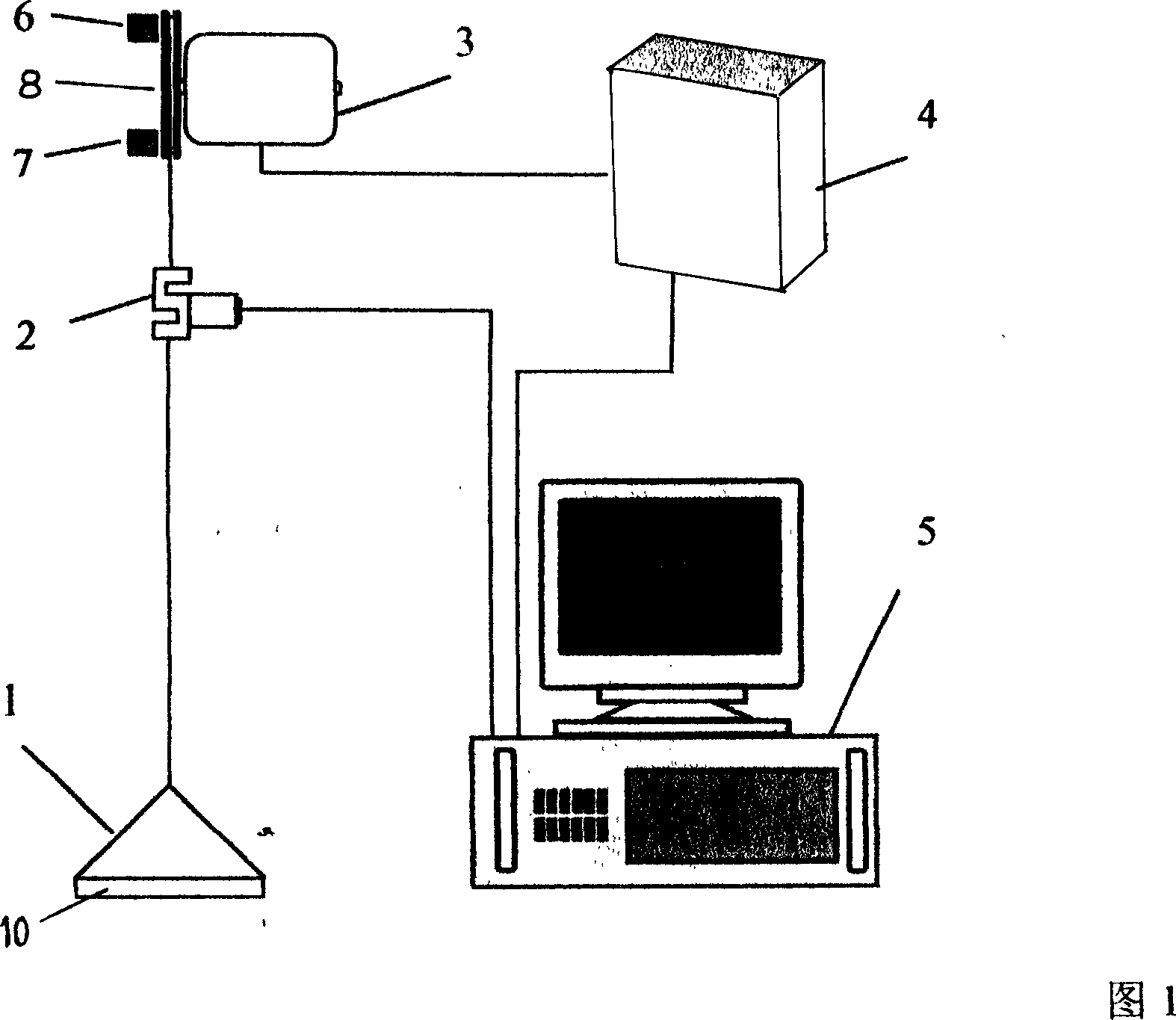
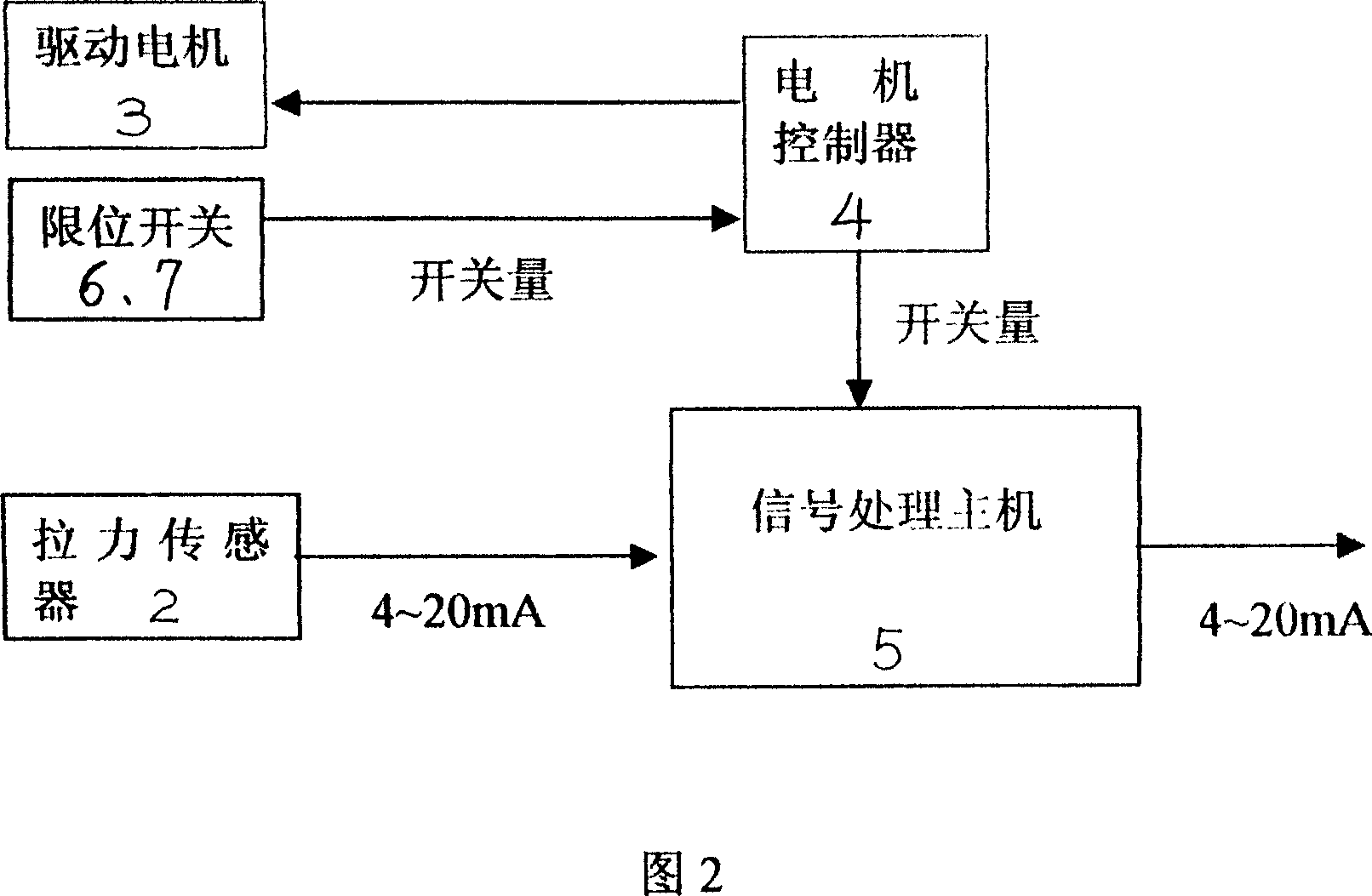
[0022] The buoyancy scanning multiphase liquid level interface detection method of the present invention will be described in detail below in combination with the structural content of the detector for implementing the method. As shown in Figure 1, the buoyancy scanning multiphase liquid level interface detector includes a signal processing host 5, a driving motor 3, a motor controller 4, a float 1, and a series connected to the pulling wire of the driving motor pulling the float 1 In the tension sensor 2, the bottom surface of the float 1 is a plane, and its overall average density is greater than the density of the liquid to be measured, and the optimum ratio of the two densities is 2:1. In this implementation structure, the upper part of the float 1 is a cone, so as to avoid depositing dirt on the float to change its quality, to keep the weight and density of the float as constant as possible, and to avoid measurement errors; The plane bottom surface of the circular cake bo...


PUM


Abstract

The invention discloses a buoyancy scanning multiphase liquid location surface detection method, and it is: vertical reciprocating the uniform speed pulling floater, and when it touching liquid location or surface, it produces pulling force mutation, and scanning to detect the mutation moment, and multiplying the floater running speed and time, then amending with the initiation location, so as to come up with the accurate liquid location or surface height value. The detecting device to implement the said detecting method includes the signal processing host, the floater, the driven motor and the pulling sensor, and the floater, whose overall average density greater than the density of measured liquid, has the flat bottom, the pulling sensor connecting on the floater traction line in series, the pulling sensor signals sending into the signal processing host through data transmission channel, the switch signals of the driven motor electrical controller connecting to the signal processing host. The technology scheme can detect the liquid location or surface under the changing conditions of the measured liquid density, and also detect the multi-media crossing surface or liquid location of different densities, each un-mixed multiple liquids and liquid-solid-coexistence, and it has the technical features of simple technical compose, accurate detection, broad application.

Description

Technical field [0001] The invention relates to a liquid level or interface measurement method and a detection instrument thereof. Background technique [0002] Existing liquid level or interface detection instruments mainly include float level gauges, ultrasonic level gauges, radar level gauges and ionizing radiation level gauges. [0003] The float level gauge is mainly composed of a float, a position sensor and an instrument host. The float is usually a hollow sphere or a cylinder. It is mainly a position measuring device when the float is in a state of equilibrium between its gravity and its buoyancy. This type of level meter can only get a single level value. In actual testing, the overall average density of the float is required to be about half of the liquid density, and half of the float is immersed under the liquid surface during floating. The technical problems of the existing float level gauge are: first, it can only be used for single liquid level detection, bu...

Claims


Application Information

Patent Timeline
IPC IPC(8): G01F23/30G01F23/40G01F23/00
Inventor 侯朝勤包良清范德日谢琼泽刘厚乾王文田王远峰
Owner DANDONG DONGFANG MEASUREMENT&CONTROL TECHCO
Why Eureka
Try Eureka