Optical sensor, ink cartridge, and inkjet apparatus

An optical sensor and ink cartridge technology, applied in the direction of using optical devices, measuring devices, scientific instruments, etc., can solve the problems of ink clogging of nozzle holes, unsmooth ink ejection action, and difficulty in ensuring subtle color tone, etc., and achieve the effect of reducing costs.

Inactive Publication Date: 2007-05-23
SEIKO EPSON CORP
View PDF3 Cites 6 Cited by
  • Summary
  • Abstract
  • Description
  • Claims
  • Application Information

AI Technical Summary

Problems solved by technology

However, although the optical sensors of Patent Documents 1 and 2 can recognize large color differences and changes in density, etc., it is difficult to ensure strict ink quality (print quality) such as subtle color tone differences.
In addition, even if ink of the same color is used, when ink with different components is used, the ink often clogs the nozzle hole or the ink ejection action is not smooth.
In addition, such a problem is not limited to recognizing the type of ink, it is a problem that occurs when recognizing various objects

Method used


Image

  • Optical sensor, ink cartridge, and inkjet apparatus
  • Optical sensor, ink cartridge, and inkjet apparatus
  • Optical sensor, ink cartridge, and inkjet apparatus

Examples


no. 1 Embodiment approach

[Inkjet device]

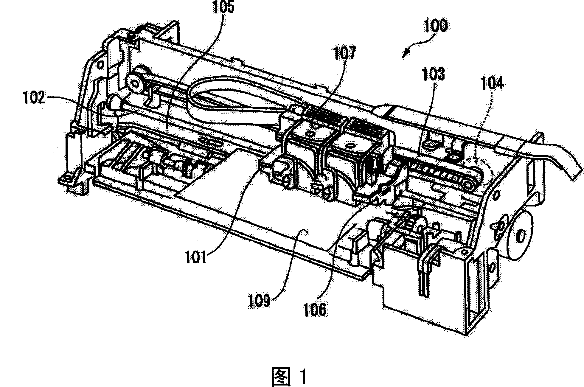
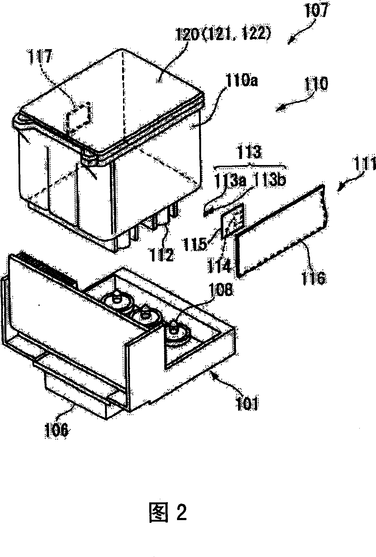
1 is a schematic perspective view showing an inkjet device including an ink cartridge according to a first embodiment of the present invention. In addition, FIG. 2 is an exploded perspective view showing main parts of a printing unit including an ink cartridge.

[0026]

As shown in FIG. 1 , an inkjet device 100 includes a carriage 101 on which ink cartridges are mounted, and an inkjet recording head 106 .

[0027]

The carriage 101 is supported by a guide member 102 and connected to a stepping motor 104 via a timing belt 103 so as to reciprocate parallel to the table 105 . An inkjet recording head 106 is mounted on the lower side of the carriage 101, and a printing unit 107 is mounted on the upper side in a detachable manner.

[0028]

As shown in FIG. 2 , the printing unit 107 includes an ink cartridge 110 and a carriage 101 on which the ink cartridge 110 is mounted.

[0029]

The carriage 101 has a box-like shape with an open top, and an inkjet record...

no. 2 Embodiment approach

In addition, FIG. 20 is an exploded perspective view showing main parts including an optical sensor 211 according to the second embodiment of the present invention. The same reference numerals are assigned to the same components as those in the first embodiment, and the description thereof will not be repeated.

[0103]

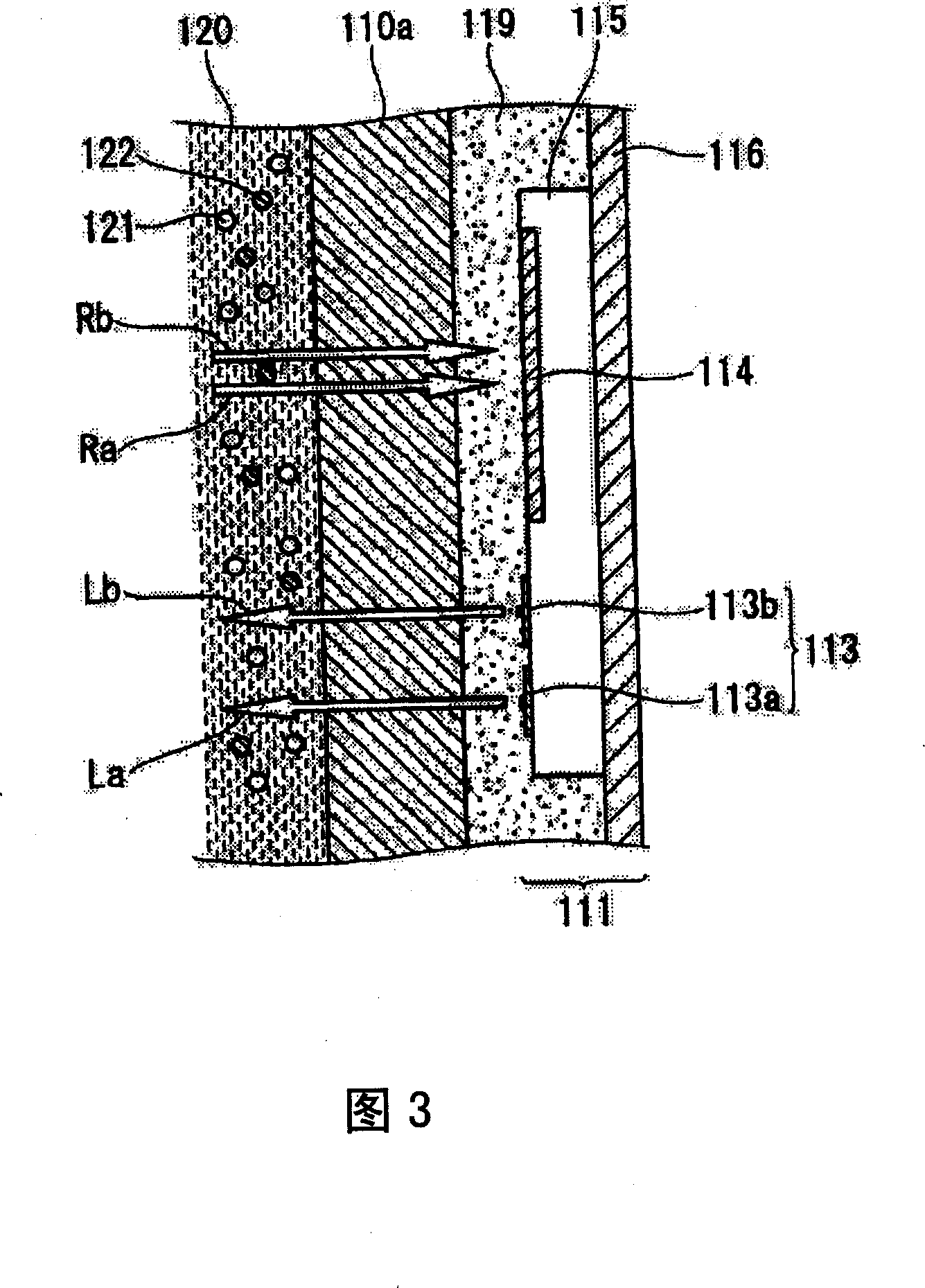
As shown in FIG. 20, there are light-emitting elements 113a, 113b for irradiating reference light to the ink in the ink cartridge 110, a light-receiving element 114 for receiving reference light transmitted through the ink in the ink cartridge 110, and a first light-emitting element electrically connected to the light-emitting elements 113a, 113b. The integrated circuit board 215 , the second integrated circuit board 214 electrically connected to the light receiving element 114 , and the printed wiring board 216 electrically connected to the first integrated circuit board 215 and the second integrated circuit board 214 .

[0104]

On the first integrated circ...


PUM

PropertyMeasurementUnit
thicknessaaaaaaaaaa
thicknessaaaaaaaaaa

Abstract

An optical sensor 111 for identifying a subject 120 in accordance with the present invention is characterized in that, it has a light emitting device 113 for radiating reference light at a subject 120, and a light receiving device 114 used for receiving the reference light transmitted through the subject 120. Said reference light with light absorption characteristics of the light receiving material 121, 122 contained in said subject 120, has a peak wavelength in an absorption wavelength region of the light absorption materials 121, 122 adjusted independently from the subject. According to the light amount of the reference light transmitting through the subject, said light receiving material 121, 122 is capable of being identified. On the basis of the identifying results, a subject120 is capable of be identified. A high precision optical sensor for identifying a subject such as ink and the like is provided.

Description

technical field [0001] The present invention relates to an optical sensor that can be used for identification of ink, etc., an ink cartridge and an inkjet device including the optical sensor. Background technique [0002] In recent years, inkjet printers have been able to achieve the same printing quality as photographs, and the durability of printed matter has also been further improved. There is no doubt that this is due to the improvement of the mechanical performance of the printer, but the improvement of the performance and quality of the ink, and the progress of the color tone control technology according to the characteristics of each ink also contributed. [0003] With the popularization of such inkjet printers, inks having various characteristics have been developed, and the types of inks have tended to diversify. In the diversification of inks, it is necessary to identify inks in order to ensure printing quality. [0004] As a method of identifying ink, f...

Claims


Application Information

Patent Timeline
Patent Type & Authority Applications(China)
IPC IPC(8): G01N21/27H01L25/16B41J2/12B41J2/01B41J2/175G01N21/35G01N21/359H01L31/12
CPCG01N21/3504B41J2/17566B41J2002/17573H01L24/83H01L2224/83001H01L2924/12042H01L2924/12041H01L2924/12043H01L2924/14H01L2924/00B41J2/17546B41J2/17506G01B11/00
Inventor 近藤贵幸原弘幸丰田直之天野和彦
Owner SEIKO EPSON CORP
Why Eureka
Try Eureka