Base plate and LCD device

A technology of liquid crystal display device and liquid crystal display panel, which is applied in static indicators, nonlinear optics, optics, etc., can solve the problems of complex structure of liquid crystal display device and the like

Inactive Publication Date: 2007-05-23
INNOCOM TECH SHENZHEN +1
View PDF1 Cites 10 Cited by
  • Summary
  • Abstract
  • Description
  • Claims
  • Application Information

AI Technical Summary

Problems solved by technology

[0008] In order to overcome the defects of the complex structure of the prior art liquid crystal display device, it is necessary to provide a liquid crystal display device with a simple structure and its substrate

Method used


Image

  • Base plate and LCD device
  • Base plate and LCD device
  • Base plate and LCD device

Examples


Embodiment Construction

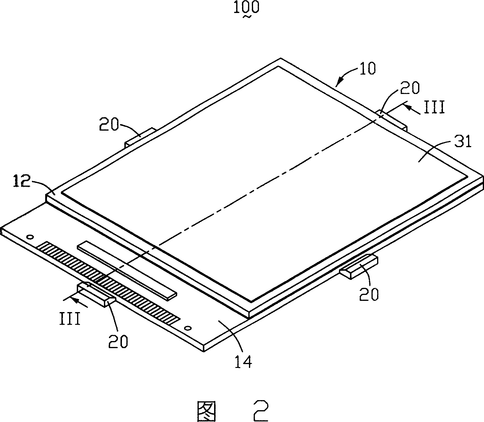
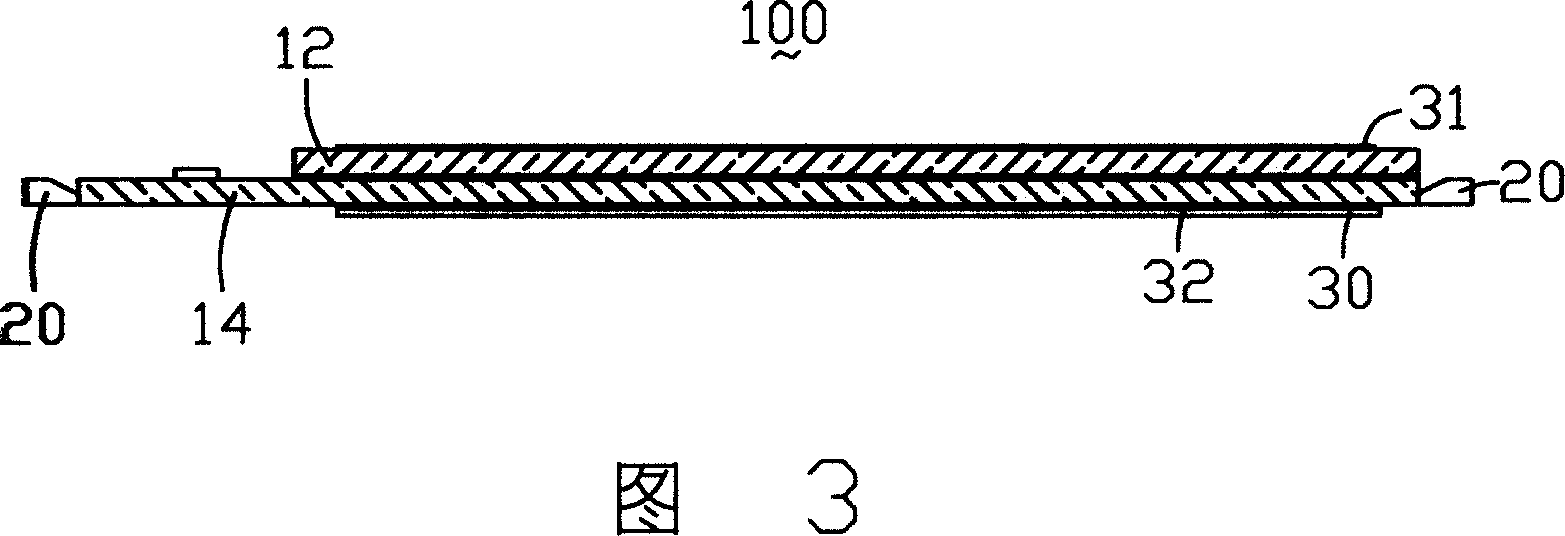
[0024] Please refer to FIG. 2 and FIG. 3 , FIG. 2 is a schematic perspective view of a liquid crystal display device according to a first embodiment of the present invention, and FIG. 3 is a schematic cross-sectional view along II-II of the liquid crystal display device in FIG. 2 . The liquid crystal display device 100 includes a liquid crystal display panel 10 and a plurality of light sources 20 .

[0025] The liquid crystal display panel 10 includes an upper substrate 12, a lower substrate 14 and a liquid crystal layer (not shown) that are arranged oppositely. The plurality of light sources 20 are four light emitting diodes (Light Emitting Diode, LED), and the four light emitting diodes Set on the four sides of the lower substrate 14, polarizers 31, 32 are respectively arranged on the outer surfaces of the two opposite substrates 12, 14, and a reflective sheet 30 is also arranged on the outside of the polarizer 32 of the lower substrate 14, and the polarizer 32 is also Refle...


PUM


Abstract

The invention discloses a liquid crystal display device and the substrate. LCD installations include an LCD panel and a light, the LCD panel including a substrate. The substrate includes many dimensions, two surfaces relative to the intersection, a display area and a marginal region. The edge of the substrate embraces a host of regional space, and the source asylum is in the asylum space. The substrate surface has a microstructure. The liquid crystal display device can be achieved light and simple purpose.

Description

【Technical field】 [0001] The invention relates to a substrate and a liquid crystal display device. 【Background technique】 [0002] Due to the advantages of lightness, thinness, and low power consumption, liquid crystal display devices are widely used in modern information equipment such as notebook computers, mobile phones, and personal digital assistants. Because the liquid crystal itself does not have light-emitting properties, it is necessary to provide a backlight device for it to realize the display function. [0003] The prior art liquid crystal display device includes a liquid crystal display panel, a backlight device and a flexible printed circuit board (Flexible Printed Circuit Board, FPC) or printed circuit board (Printed Circuit Board, PCB) assembly, etc., and the backlight device includes a light source and The light guide plate and the light source are arranged relative to the light incident surface of the light guide plate. The light guide plate guides the tra...

Claims


Application Information

Patent Timeline
Patent Type & Authority Applications(China)
IPC IPC(8): G02F1/133G02F1/1335
Inventor 吕嵩张志弘林精皇
Owner INNOCOM TECH SHENZHEN
Why Eureka
Try Eureka