Direct current current-limiting device of neutral point of grounding transformer

A grounding transformer, DC current technology, applied in circuit devices, emergency protection circuit devices, emergency protection circuit devices for limiting overcurrent/overvoltage, etc. Inflow, complex structure and other problems, to achieve the effect of simple structure, volume reduction, and structure simplification

Active Publication Date: 2007-05-23
HUAZHONG UNIV OF SCI & TECH
View PDF0 Cites 27 Cited by
  • Summary
  • Abstract
  • Description
  • Claims
  • Application Information

AI Technical Summary

Problems solved by technology

Although this method is simple in principle, it also has many disadvantages: a. It cannot completely suppress the inflow of DC from the neutral point; Conditions, soil moisture content, mineral content, buried metal and many other influencing factors can...

Method used


Image

  • Direct current current-limiting device of neutral point of grounding transformer

Examples


Embodiment Construction

[0014] Below in conjunction with accompanying drawing and example the present invention is described in further detail.

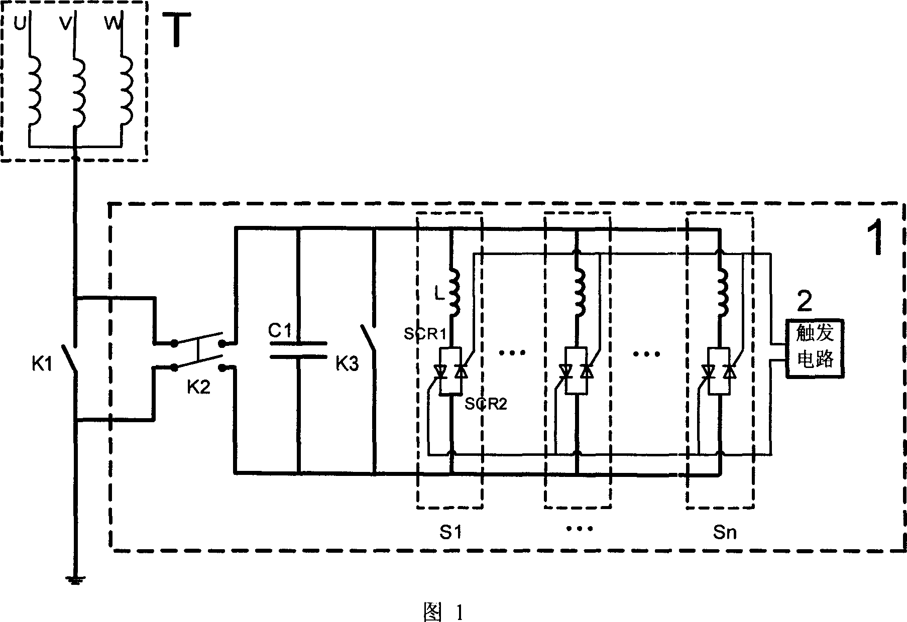
[0015] As shown in Figure 1, the current suppression device 1 of the present invention includes a capacitor C1, switches K2, K3, a trigger circuit 2 and n groups of parallel bidirectional thyristor solid state switches S1, S2,..., Sn, wherein n is a parallel bidirectional thyristor solid state switch number, n≥1. In the figure, T is a transformer, and switch K1 is a direct grounding knife switch for the neutral point of the transformer.

[0016] The switch K2 is connected in parallel at both ends of the neutral point grounding switch K1 of the transformer T, and is a switching switch for suppressing the DC current device at the neutral point of the transformer;

[0017] Capacitor C1 is connected in parallel at both ends of switch K2. Under the normal working condition of the device, it prevents DC current from flowing from the ground to the neutral point o...


PUM


Abstract

The invention relates to a neutral point direct-current restrainer of ground transformer, wherein it comprises blocking capacitor, thyristor solid switch connected to two ends of blocking capacitor, relative trigger unit, limit resistance, and bypass switch. The invention can effective restrain the neutral point direct current caused by high-voltage direct current, etc, to reduce noise, overheat, etc. And it has simple process and low cost, without external reverse voltage.

Description

technical field [0001] The invention belongs to the technical field of electrical engineering, and in particular relates to a neutral point direct current suppression device for a grounding transformer. Background technique [0002] High-voltage direct current transmission (HVDC) is more and more used in my country, and it plays a very active role in the interconnection of regional power systems, but it also brings some new problems, for example, the transformer DC caused by the asymmetric operation of HVDC. Bias problem. Therefore, it is necessary to develop a device that can inhibit the DC current from flowing into the neutral point of the transformer, so as to effectively avoid the DC bias phenomenon of the transformer. [0003] When the HVDC operates in the unipolar ground return line or the bipolar asymmetric operation mode, there is a DC potential near the ground electrode, which is related to the magnitude of the current delivered by the HVDC and the soil resistivity ...

Claims


Application Information

Patent Timeline
IPC IPC(8): H02H7/04H02H9/02
Inventor 毛承雄陆继明王升王丹
Owner HUAZHONG UNIV OF SCI & TECH
Why Eureka
Try Eureka