
Receiver and its decoding method

A technology of receiver and modulation mode, which is applied in the direction of multi-frequency code system, baseband system components, etc., can solve the problem of prolonging the receiver's processing time of data information, increasing the complexity of the modulation mode detection module, and increasing the last two burst detection errors problems such as avoiding the probability of correct decoding, shortening the time for processing data information, and reducing the amount of information storage

Active Publication Date: 2007-05-23
HONOR DEVICE CO LTD
View PDF0 Cites 1 Cited by
  • Summary
  • Abstract
  • Description
  • Claims
  • Application Information

AI Technical Summary

Problems solved by technology

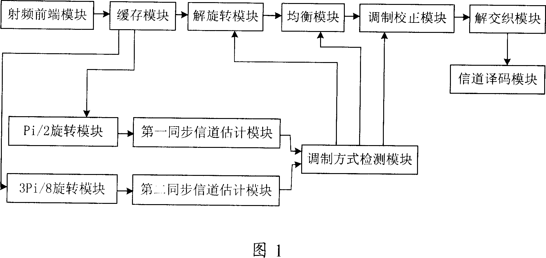
[0006] 1. To detect the modulation modes of the four bursts in each block requires a large amount of calculation and high detection complexity, thus reducing the performance of the receiver and increasing the delay of information processing; and , each time it is necessary to detect the modulation modes of the last two bursts in a block, and the modulation modes of the last two bursts may be detected incorrectly, which increases the probability of detection errors of the last two bursts, and the modulation correction When the module processes the burst, it will clear the soft value of one or two bursts different from the determined modulation mode, which will reduce the probability of correct decoding;
[0007] 2. In addition, the modulation mode information of four bursts needs to be stored in the modulation mode detection module each time, so as to determine the modulation mode of the block through the statistics and analysis of the modulation modes of each burst, which requires a certain The amount of calculation will prolong the time for the receiver to process data information, which will also reduce the performance of the receiver and increase the delay of information processing. Moreover, storing the modulation mode information in the modulation mode detection module will occupy a certain storage space , which will increase the complexity of the modulation detection module

Method used


Image

  • Receiver and its decoding method
  • Receiver and its decoding method
  • Receiver and its decoding method

Examples


Embodiment Construction

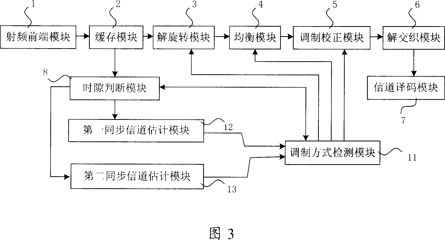
[0044] Figure 3 is a schematic structural diagram of a receiver embodiment 1 of the present invention, the receiver includes a radio frequency front-end module 1, a buffer module 2, a derotation module 3, an equalization module 4, a modulation correction module 5, a deinterleaving module 6 and The channel decoding module 7 also includes a time slot judging module 8 connected to the derotation module 3, and a first synchronous channel estimation module 12 and a second synchronous channel estimation module 13 connected to the time slot judging module 8 at the same time, and simultaneously The modulation scheme detection module 11 connected with the first synchronous channel estimation module 12 and the second synchronous channel estimation module 13, the modulation scheme detection module 11 is also respectively connected with the derotation module 3, the equalization module 4, the modulation correction module 5 and the slot judgment module 8 connect. Among them, the radio frequ...


PUM


Abstract

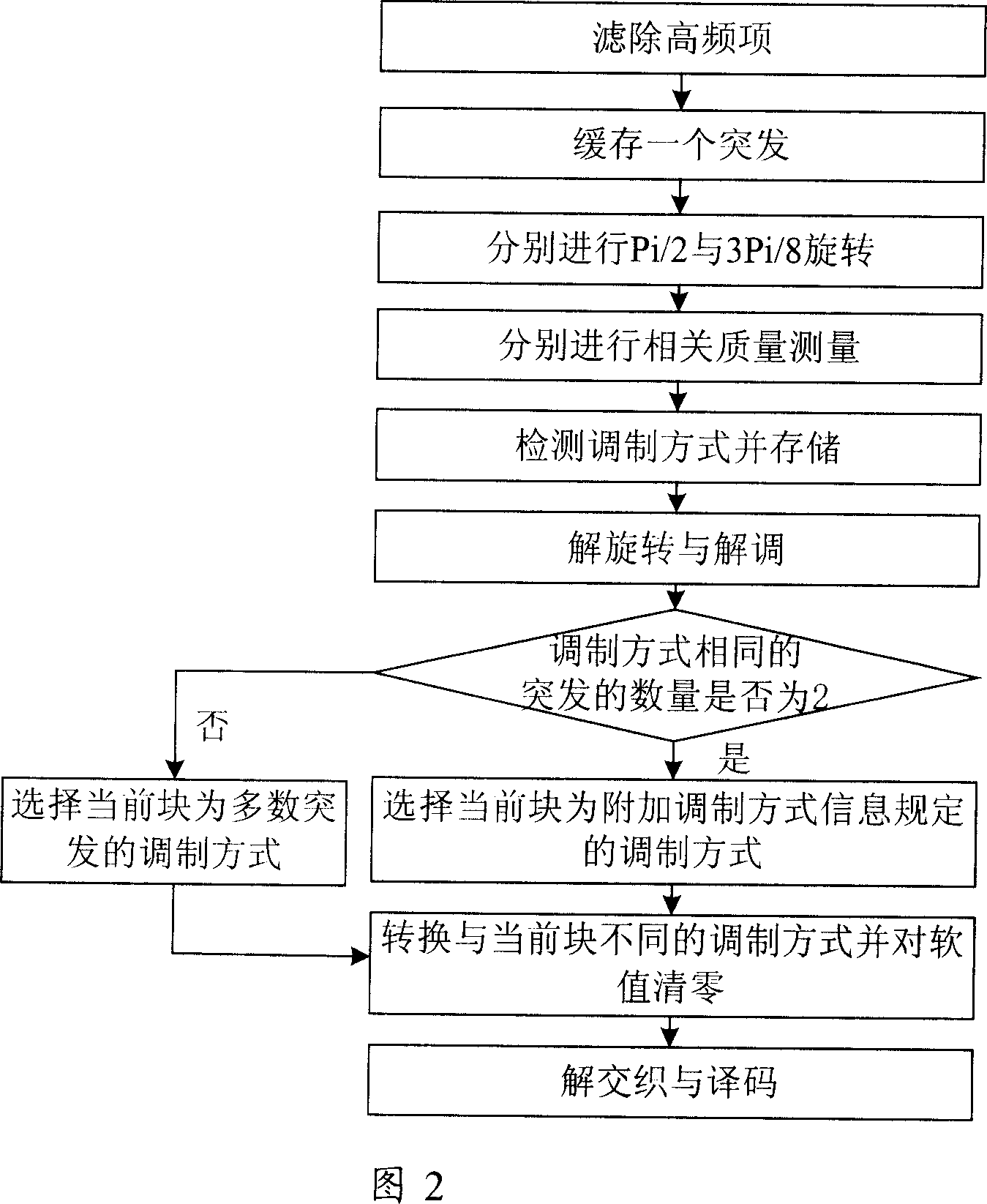
The invention relates to a receiver and decoding method, wherein said decode method comprises that: filtering out the high-frequency component of received signal, to obtain one burst to be buffered; judging the sequence of burst in data block; checking the front X bursts of four bursts of data block, to obtain the modulation method of front X bursts, while X is not lower than 2 but lower than 4; based on the modulation method of front X burst modulations, predicting the modulation methods of left 4-x bursts; based on the modulations of four bursts, finding the modulation method of data block. The invention can reduce information memory amount, save memory space, reduce the complexity of modulation correcting module, etc.

Description

technical field [0001] The invention relates to a wireless information processing technology, in particular to a receiver and a decoding method thereof. Background technique [0002] In some cellular communication systems, different modulation methods can be advantageously used, such as: 8-PSK (Phase Shifi Keying, phase shift keying) and GMSK (Gaussian Minimum Shift Keying, Gaussian Minimum Shift Keying), in the transmission Exchange information between a machine (such as a base station) and a receiver (such as a mobile station or a fixed cellular terminal), for example: Enhanced Data rates for GSM (Global System for Mobile communication, Global System for Mobile Communications) evolution (Enhanced Data rates for GSMEvolution , EDGE) system, which supports two modulation modes of linear 8-PSK and GMSK. In the packet data transmission mode of EDGE, 8-PSK can use 5 different coding rates for coding, while GMSK can use 4 different coding rates. to encode. These different enco...

Claims


Application Information

Patent Timeline
Patent Type & Authority Applications(China)
IPC IPC(8): H04L27/26H04L25/02
Inventor 陈俊仕江长国冯淑兰
Owner HONOR DEVICE CO LTD
Learn More