Printing oil ink and production method of coating film using the oil ink
A technology of ink and printing plate, which is applied in the field of printing ink and the coating film using the ink, and can solve the problems of complicated process and unremovable
- Summary
- Abstract
- Description
- Claims
- Application Information
AI Technical Summary
Problems solved by technology
Method used
Image
Examples
Embodiment A1~A23
[0032]
[0033] Mix the powder components, resin components, solvent components and dispersants shown in the following Tables 1 to 5 with a mixer, and further perform pulping at about 5 to 10 Pa·s with a three-roll mill, thereby obtaining a paste printing with ink.
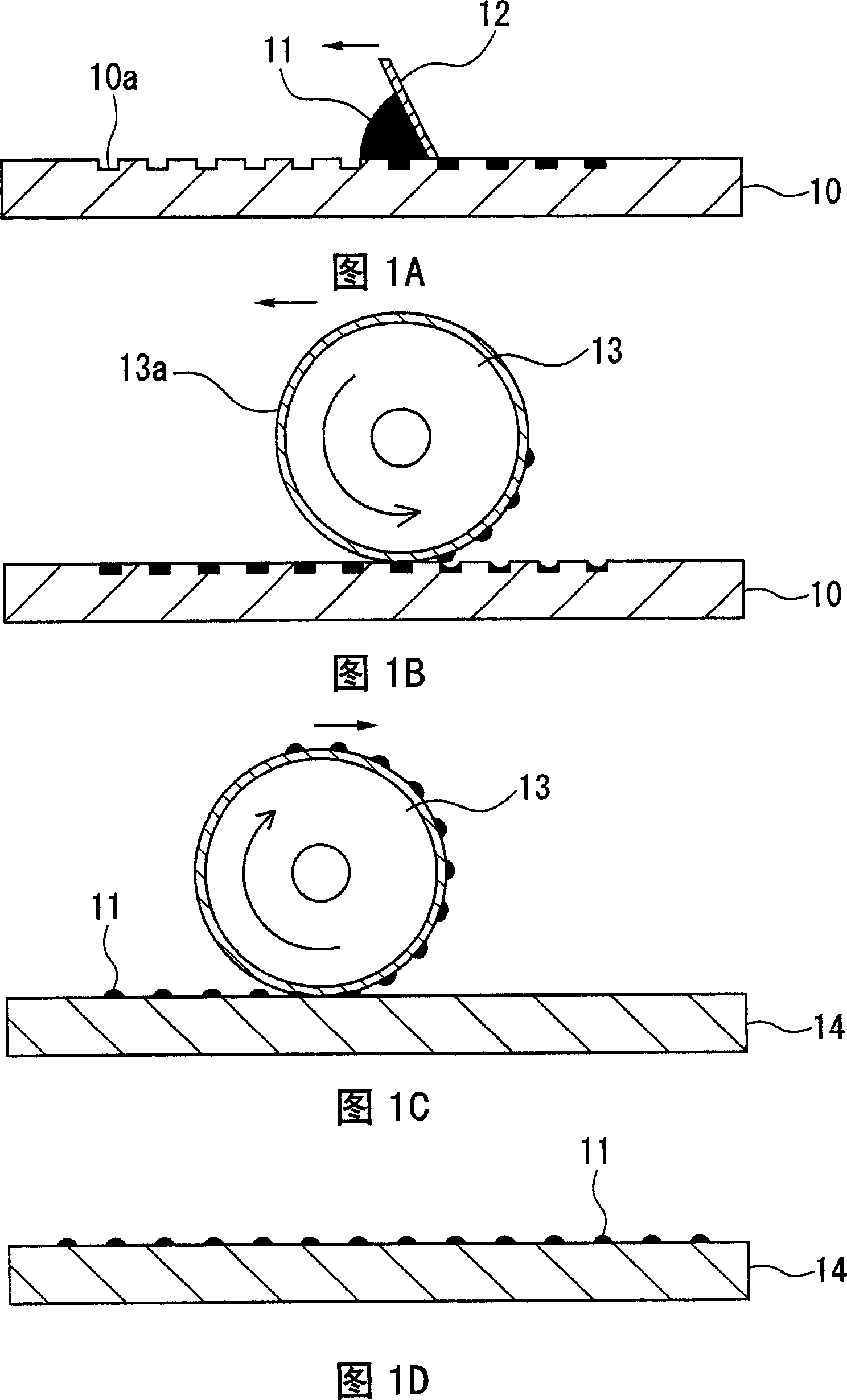
[0034] As a printing plate for gravure offset printing, a 42-alloy flat gravure plate having a plurality of concave patterns having a line width of 100 μm, a depth of 25 μm, and a pitch of 360 μm was prepared, and a glass substrate was prepared as a transfer target. In addition, a blanket roll having a 0.3 mm-thick silicone resin sheet attached to its surface was used as a printing blanket. First, the obtained printing ink was supplied quantitatively to the surface of the intaglio plate, and the ink was embedded in the concave pattern of the intaglio plate using a SUS squeegee. Then, the blanket roller is rotated in a state of being pressed against the planar gravure, and the planar gravure is slid to transfer ...
comparative test 1
[0046] Among the 500 printed substrates obtained in Examples A1 to A23 and Comparative Example A1, for the 1st, 100th, 200th, 300th, 400th, and 500th substrates, measure the Calculate the average value and standard deviation of the measured values for the line widths at 9 points at predetermined positions. The results are shown in Tables 6 to 8.
[0047] 【Table 6】
[0048] Example A1
Example A2
Example A3
Example A4
Example A5
Example A6
Example A7
Example A8
Example A9
unit
[μm]
Ave.
σ
Ave.
σ
Ave.
σ
Ave.
σ
Ave.
σ
Ave.
σ
Ave.
σ
Ave.
σ
Ave.
σ
1st piece
102.5
7.9
101.7
6.7
100.4
4.8
101.7
5.0
102.1
4.2
101.2
4.3
101.8
4.3
100.9
4.4
101.8
3.9
100th tablet
95.3
4.2
92.4
...
Embodiment B1~B23
[0068]
[0069] The powder components, resin components, solvent components, and dispersants shown in Tables 9 to 32 below were mixed with a mixer, and further squeezed at about 5 to 10 Pa·s with a three-roll mill to obtain printing inks.
[0070]A 42-alloy planogravure plate having a plurality of concave patterns having a line width of 100 μm, a depth of 25 μm, and a pitch of 360 μm was prepared as a printing plate for offset printing, and a glass substrate was prepared as a transfer target. In addition, as a printing blanket, a blanket roll having a silicone rubber sheet having a thickness of 0.3 mm attached to its surface was used. First, the obtained printing ink was supplied quantitatively to the surface of the intaglio plate, and the ink was embedded in the concave pattern of the intaglio plate using a SUS squeegee. Then, the blanket roller is rotated in a state of being pressed against the planar gravure, and the planar gravure is slid to transfer a part of the ink em...
PUM
| Property | Measurement | Unit |
|---|---|---|
| depth | aaaaa | aaaaa |
Abstract
Description
Claims
Application Information
 - R&D
- Intellectual Property
- Life Sciences
- Materials
- Tech Scout
- Unparalleled Data Quality
- Higher Quality Content
- 60% Fewer Hallucinations
Browse by: Latest US Patents, China's latest patents, Technical Efficacy Thesaurus, Application Domain, Technology Topic, Popular Technical Reports.
© 2025 PatSnap. All rights reserved.Legal|Privacy policy|Modern Slavery Act Transparency Statement|Sitemap|About US| Contact US: help@patsnap.com

