Printing oil ink and production method of coating film using the oil ink

A technology of ink and printing plate, which is applied in the field of printing ink and the coating film using the ink, and can solve the problems of non-removal and complicated process

Active Publication Date: 2012-09-12
MITSUBISHI MATERIALS CORP
View PDF2 Cites 1 Cited by
  • Summary
  • Abstract
  • Description
  • Claims
  • Application Information

AI Technical Summary

Problems solved by technology

[0005] However, the methods described in the above-mentioned Patent Documents 1 and 2 are cumbersome due to the addition of heating and cooling steps in the usual gravure offset printing, and cannot prevent the solvent in the ink from permeating the silicon on the surface of the blanket due to printing. In rubber sheet, there is no solution to the underlying problem

Method used


Image

  • Printing oil ink and production method of coating film using the oil ink
  • Printing oil ink and production method of coating film using the oil ink
  • Printing oil ink and production method of coating film using the oil ink

Examples


Embodiment A1~A23

[0032]

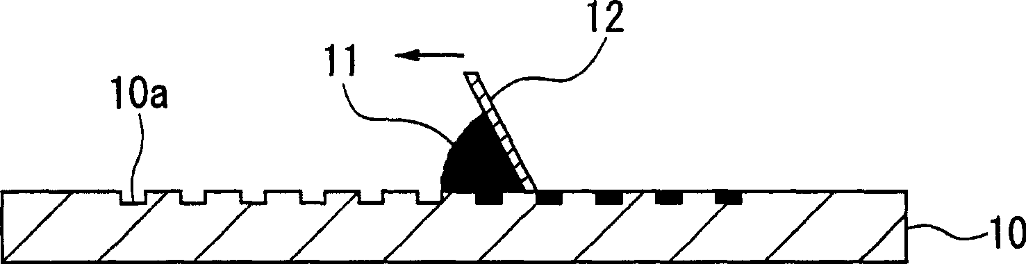
[0033] Mix the powder components, resin components, solvent components and dispersants shown in the following Tables 1 to 5 with a mixer, and further perform pulping at about 5 to 10 Pa·s with a three-roll mill, thereby obtaining a paste printing with ink.

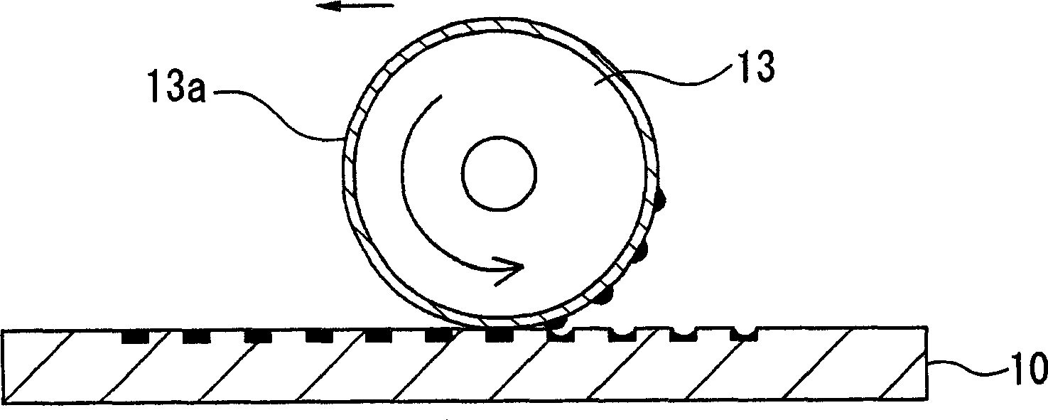
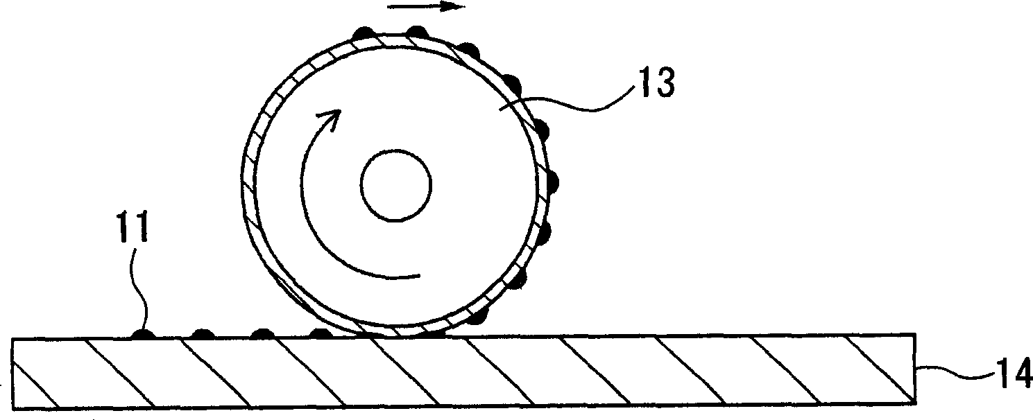
[0034] As a printing plate for gravure offset printing, a 42-alloy flat gravure plate having a plurality of concave patterns having a line width of 100 μm, a depth of 25 μm, and a pitch of 360 μm was prepared, and a glass substrate was prepared as a transfer target. In addition, a blanket roll having a 0.3 mm-thick silicone resin sheet attached to its surface was used as a printing blanket. First, the obtained printing ink was supplied quantitatively to the surface of the intaglio plate, and the ink was embedded in the concave pattern of the intaglio plate using a SUS squeegee. Then, the blanket roller is rotated in a state of being pressed against the planar gravure, and the planar gravure is slid to transfer ...

comparative test 1

[0047] In each of the 500 printed substrates obtained in Examples A1 to A23 and Comparative Example A1, for the 1st, 100th, 200th, 300th, 400th and 500th substrates, measure the Calculate the average value and standard deviation of the measured values ​​for the line widths at 9 points at predetermined positions. The results are shown in Tables 6 to 8.

[0048] 【Table 6】

[0049]

[0050] 【Table 7】

[0051]

[0052] 【Table 8】

[0053]

[0054] As can be seen from Tables 6 to 8, in Comparative Example A1, the average value of the line widths at nine predetermined positions on each substrate fluctuated due to the difference in the number of sheets printed continuously, and the printing stability was poor. Furthermore, a print failure occurred at the time of continuous printing of the 500th sheet. On the other hand, in Example A1 to Example A23 using the printing ink of the present invention, the average value of the line width was stable, and it was preferably used f...

Embodiment B1~B23

[0069]

[0070] The powder components, resin components, solvent components, and dispersants shown in Tables 9 to 32 below were mixed with a mixer, and further squeezed at about 5 to 10 Pa·s with a three-roll mill to obtain printing inks.

[0071]A 42-alloy planogravure plate having a plurality of concave patterns having a line width of 100 μm, a depth of 25 μm, and a pitch of 360 μm was prepared as a printing plate for offset printing, and a glass substrate was prepared as a transfer target. In addition, as a printing blanket, a blanket roll having a silicone rubber sheet having a thickness of 0.3 mm attached to its surface was used. First, the obtained printing ink was supplied quantitatively to the surface of the intaglio plate, and the ink was embedded in the concave pattern of the intaglio plate using a SUS squeegee. Then, the blanket roller is rotated in a state of being pressed against the planar gravure, and the planar gravure is slid to transfer a part of the ink em...


PUM

PropertyMeasurementUnit
depthaaaaaaaaaa

Abstract

The present invention provides a printing ink can reduce shape changes of printing pattern in consecutive printing using gravure offset printing. Said printing ink is used in gravure offset printing. In gravure offset printing, this ink is filled in printing plates with concave pattern, transfer filled ink to blankets for printing which have silicone rubber on surface, transfer ink from blankets to transferrer. Said printing ink at least includes powder component which comprise inorganic or organic powder, when including one or two kinds of rosin and solvent component which selected from group consist of acrylic resin and methyl acrylic resin, solvent component comprising more than one or two kinds of glycols solvent.

Description

technical field [0001] The present invention relates to a printing ink suitable for gravure offset printing for forming a fine and high-precision electrode pattern on a semiconductor device, and a method for producing a coating film using the ink. Background technique [0002] The formation of electrodes in semiconductor devices such as circuit boards and display devices has been using photolithography. However, this photolithography method requires a lot of equipment due to the complexity of the manufacturing process, large material loss, and the exposure equipment necessary for pattern formation. Therefore, there is a problem that the manufacturing cost is very high. Furthermore, the cost of processing waste liquid generated in the development process etc. at the time of pattern formation is also high, and this waste liquid also has a problem in terms of environmental protection. [0003] Therefore, various studies have been made on pattern forming methods that are low-co...

Claims


Application Information

Patent Timeline
Patent Type & Authority Patents(China)
IPC IPC(8): C09D11/10B41N1/24B41M1/10B41M1/34C09D11/107G03F7/027
CPCB41M1/34C09D11/02C09D11/033C09D11/106G03F7/027
Inventor 植杉隆二
Owner MITSUBISHI MATERIALS CORP
Why Eureka
Try Eureka