Electromagnetic-rheological fluid hydro-pneumatic hanging system

A technology of rheological fluid and oil-air suspension, which is applied in the direction of suspension, elastic suspension, vibration suppression adjustment, etc., can solve problems such as difficulties, practical application difficulties, and increase the cost of automobile suspension systems, so as to improve competitiveness and improve reliability performance , Reduce the effect of primary investment cost and use cost

Inactive Publication Date: 2007-05-30
吕崇耀
View PDF2 Cites 11 Cited by
  • Summary
  • Abstract
  • Description
  • Claims
  • Application Information

AI Technical Summary

Problems solved by technology

However, the application of electromagnetic rheological technology also makes the connection of traditional oil-pneumatic springs (such as US2004113377 Hydro-pneumatic Suspension System oil-air suspension system; US20050067239 Hydro-pneumatic Suspension System oil-air suspension system) relatively difficult, unless the entire system uses electromagnetic rheological fluid
[0004] Although the Chinese patent application (CN200510057020.3 Controllable Automotive Magnetorheological Shock Absorber with Vehicle Height Adjustment Function) is an example of the use of electromagnetic rheological fluid in the entire system, which adopts the known electromagnetic rheological bridge technology, which can realize the However, for four-wheeled vehicles, at least 16 electromagnetic rheological valves will undoubtedly increase the cost of the automobile suspension system and reduce the reliability of the entire system, making practical application difficult

Method used


Image

  • Electromagnetic-rheological fluid hydro-pneumatic hanging system
  • Electromagnetic-rheological fluid hydro-pneumatic hanging system
  • Electromagnetic-rheological fluid hydro-pneumatic hanging system

Examples


Embodiment Construction

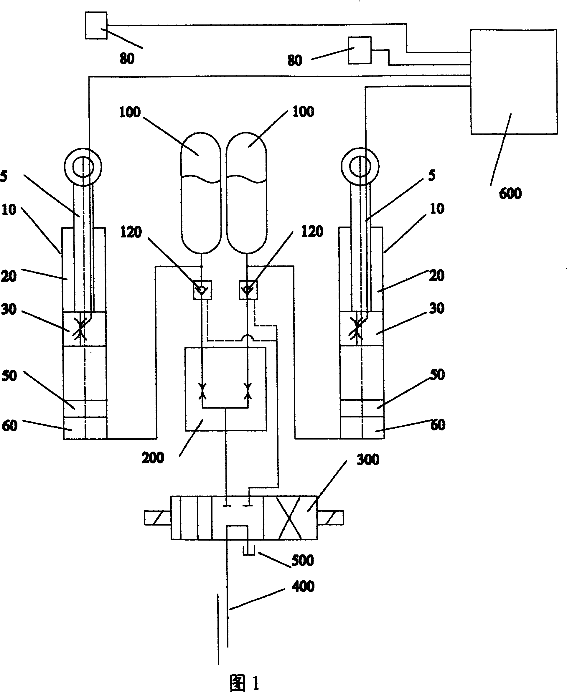
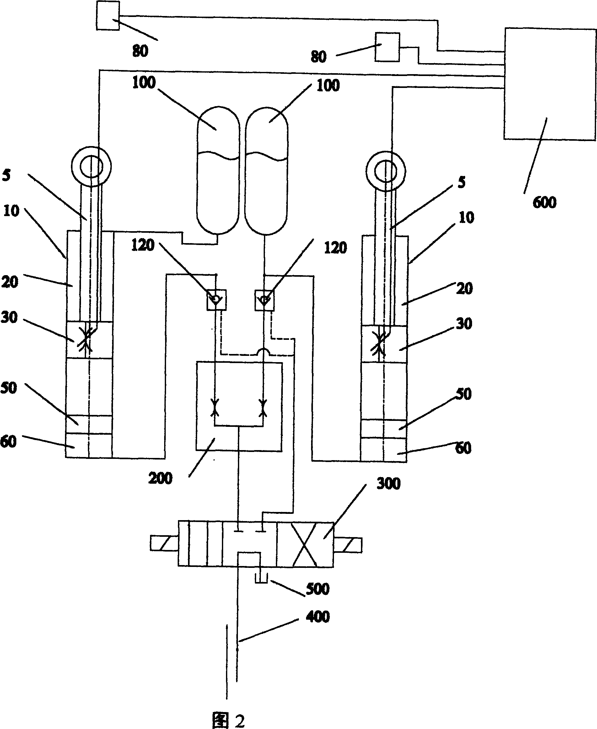
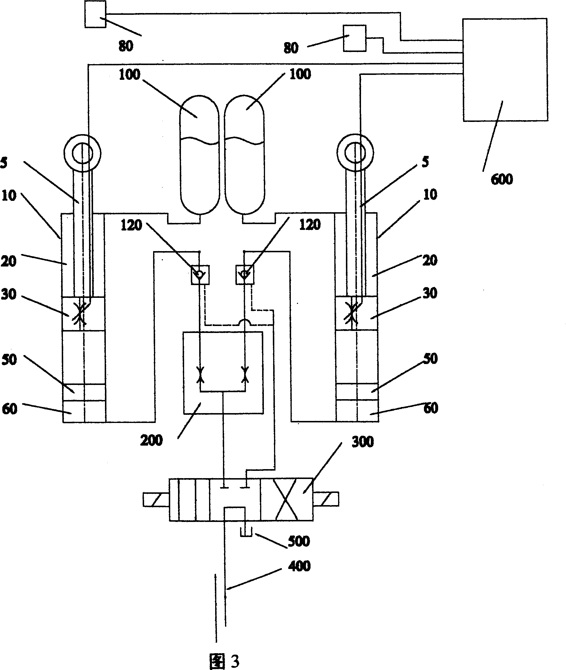
[0037] The composition and principle of an electromagnetic rheological fluid oil-air suspension system of the present invention will be described in detail below with reference to FIGS. 1-17 :

[0038] Referring to Figures 1 to 9, an electromagnetic rheological fluid oil-gas suspension system is composed of an electromagnetic rheological fluid oil-gas damping branch system and an auxiliary hydraulic synchronous branch system; the electromagnetic rheological fluid oil-gas damping branch system is It consists of an electromagnetic rheological fluid oil-gas shock absorber (10), a sensor (80) located on a controlled object, and a controller (600) for providing execution signals for the electromagnetic rheological fluid oil-gas shock absorber (10); the The auxiliary hydraulic synchronous branch system described above is composed of a diverting and collecting valve (200), a directional control valve (300) and a hydraulic oil source (400); it is characterized in that: the electromagne...


PUM


Abstract

The invention relates to a hydro-pneumatic suspension system with electromagnetic rheological fluid. As the cubage compensation cavity formed by floating piston is connected with bypass oil channel of said dividing-combining valve in the hydro-pneumatic damper, said floating piston makes the electromagnetic rheological fluid in the hydro-pneumatic damping subsystem with electromagnetic rheological fluid and the fluid for conventional hydraulic transmission in assistant hydraulic synchronization subsystem block off and makes said hydro-pneumatic damping subsystem with electromagnetic rheological fluid and said assistant hydraulicsynchronization subsystem couple so that the hydro-pneumatic damper with electromagnetic rheological fluid and two totally different driving mediums of electromagnetic rhelogical fluid and the fluid for convention hydraulic transmission are made full use of, and active variable damper ratio control, active variable stiffness control and active adjusting high synchronization control for said controlled object are realized in the same time or respectively.

Description

Technical field [0001] The present invention relates to the oil-air suspension system of vehicles and equipment, especially the active oil-air suspension system of electromagnetic rheological fluid, especially the active damping ratio control, active variable stiffness control and active height adjustment of the electromagnetic rheological fluid active oil-air suspension system. Highly synchronized control. Background technique [0002] For traditional oil-air suspension systems, there are various forms of communication. At present, many functions of the oil and gas system, such as height adjustment function, active force control function, active vibration reduction and other functions, can be realized through hydraulic components such as hydraulic servo control valve, hydraulic proportional control valve and high-speed switching valve, sensors and controllers. However, due to the large number of connected pipelines, sensors and proportional control components in the system...

Claims


Application Information

Patent Timeline
Patent Type & Authority Applications(China)
IPC IPC(8): F16F9/53B60G17/015B60G17/08
Inventor 吕崇耀
Owner 吕崇耀
Why Eureka
Try Eureka