Method forming via hole that utilizes lazer drill

A technology of laser drilling and vias, which is applied to the removal of conductive materials by chemical/electrolytic methods, the processing of insulating substrates/layers, and printed circuits. It can solve the problems of long processing time, increased processing difficulty, and via-hole Surface unevenness and other problems, to achieve the effect of shortening the processing time, ensuring uniformity, and reducing the phenomenon of electroplating defects

Inactive Publication Date: 2007-05-30
SAMSUNG ELECTRO MECHANICS CO LTD
View PDF0 Cites 6 Cited by
  • Summary
  • Abstract
  • Description
  • Claims
  • Application Information

AI Technical Summary

Problems solved by technology

[0014] However, when laser drilling is used to form via holes, the copper clad laminate using the above-mentioned prepreg needs to be processed while burning glass fibers compared with the existing RCC products without compensating materials, which increases the processing cost. Difficulty, and there is a problem of long processing time
[0015] In addition, due to processing while burning glass fiber, the side surface of the formed via hole is not uniform, resulting in poor plating problems

Method used


Image

  • Method forming via hole that utilizes lazer drill
  • Method forming via hole that utilizes lazer drill
  • Method forming via hole that utilizes lazer drill

Examples


Embodiment Construction

[0024] Preferred embodiments of the present invention will be specifically described below with reference to the accompanying drawings.

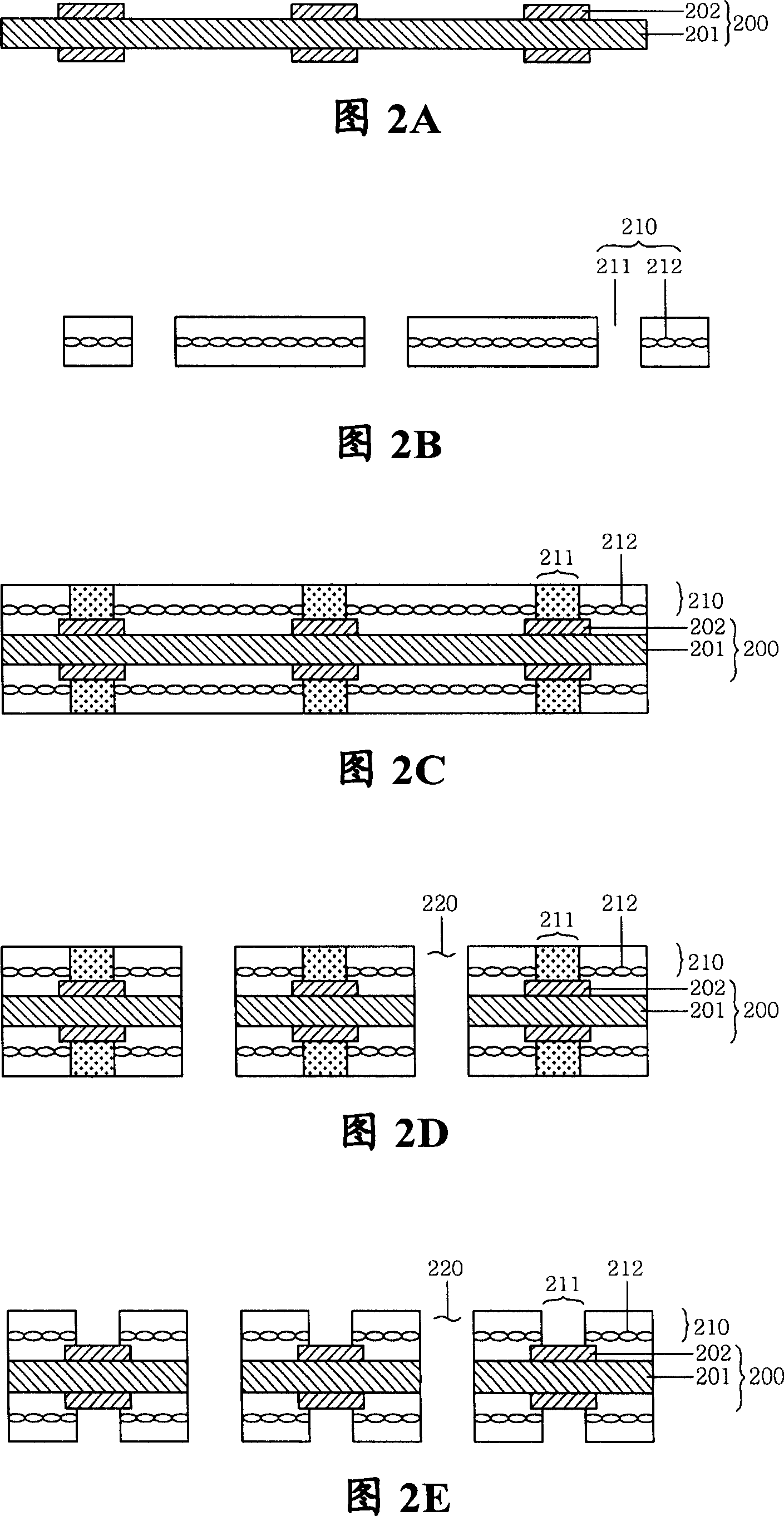
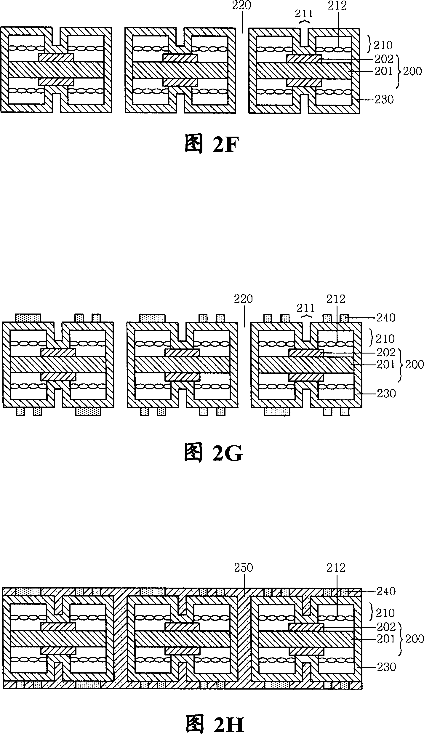
[0025] 2A to 2J are flowcharts of a via hole forming method using a laser drilling machine according to an embodiment of the present invention.

[0026] First, as shown in FIG. 2A , a first circuit board 200 in which circuits 202 are formed on both surfaces of an insulating layer 201 is prepared. In this case, any of prepreg or resin may be used for the insulating layer 201 , and common electrolytic copper foil is used for the circuit 202 .

[0027] Next, as shown in FIG. 2B , a plurality of prepregs 210 drilled with holes are prepared by mechanical drilling at positions where via holes 211 are to be formed. The above-mentioned prepreg 210 is a sheet-shaped raw material (see FIG. 3 ) in which a thermosetting resin is permeated into a base material such as glass fiber and cured to a B stage (B stage refers to a semi-cured state of the resin)...


PUM


Abstract

The invention provides a method for forming via holes by using a laser driller, the method comprises: (a) preparing to form a first circuit substrate having circuits on two sides of an insulative layer; (b) preparing to drill a plurality of prepregs having holes by automatically drilling on positions at which via holes are to be formed; (c) cumulating the prepregs on the two sides on which the first circuit substrate is formed; and (d) machining the via hole postions filled with resins flowed out from the prepregs in the step (c) by the laser driller so as to form the via holes.

Description

technical field [0001] The present invention relates to a method of forming a via hole using a laser drilling machine. More specifically, the present invention relates to a method of laminating a plurality of prepregs on both sides of a circuit substrate circuit, and then, using a laser Drilling machine A method in which a plurality of prepregs are mechanically drilled at the position where the via hole is to be formed by processing the position of the via hole that is filled with the resin flowing from the prepreg during lamination to form a via hole And drill holes. Background technique [0002] In recent years, with the rapid digitalization and networking of the electronics industry, electronic equipment has been required to achieve miniaturization, light weight, thinner shape, and higher performance. As a result, electronic equipment components have also achieved high integration and ultra-thin reduction. [0003] Therefore, a printed circuit board on which highly integ...

Claims


Application Information

Patent Timeline
Patent Type & Authority Applications(China)
IPC IPC(8): H05K3/06H05K3/00
CPCH05K3/0026H05K3/0044H05K3/0055H05K3/181
Inventor 金癸洙金载国李先镐俞贤珍
Owner SAMSUNG ELECTRO MECHANICS CO LTD
Why Eureka
Try Eureka