Gear mechanism, planetary gear device, rotating bearing device, and magical planetary gear speed reducer

A technology of planetary gears and gear mechanisms, which is applied to gear transmissions, bearings for rotational motion, bearings, etc., and can solve problems such as increased friction loss

Inactive Publication Date: 2007-05-30
View PDF1 Cites 19 Cited by
  • Summary
  • Abstract
  • Description
  • Claims
  • Application Information

AI Technical Summary

Problems solved by technology

Therefore, similar to the above, there is a problem that the frictional loss increases

Method used


Image

  • Gear mechanism, planetary gear device, rotating bearing device, and magical planetary gear speed reducer
  • Gear mechanism, planetary gear device, rotating bearing device, and magical planetary gear speed reducer
  • Gear mechanism, planetary gear device, rotating bearing device, and magical planetary gear speed reducer

Examples


no. 2 Embodiment approach

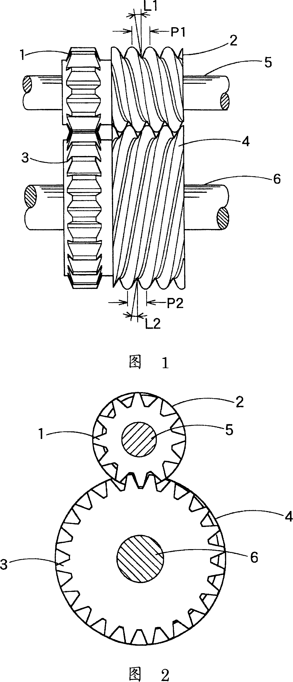
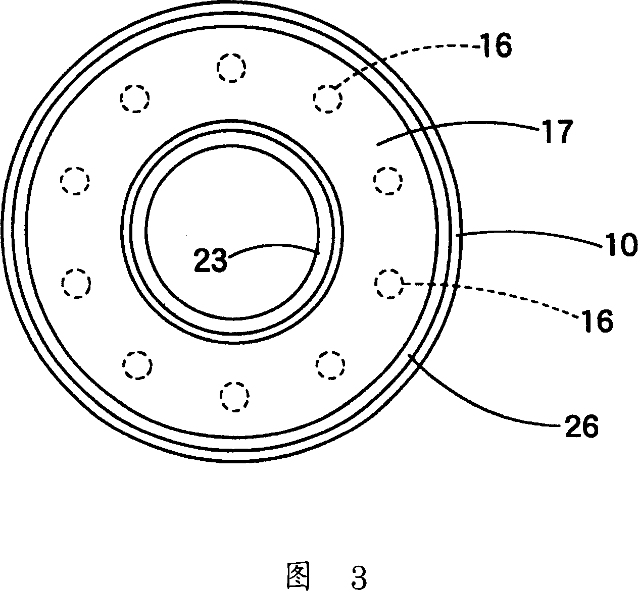
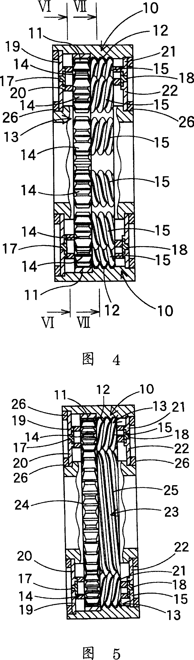
[0077] Next, a planetary gear device using the above-mentioned gear mechanism will be described with reference to FIGS. 3 to 11 . As shown in FIGS. 3 to 11 , the planetary gear unit is a one-stage planetary gear unit, and basically consists of a sun gear 23 having a sun spur gear 24 , an internal gear 10 having an internal spur gear 11 , and a planetary spur gear 14 . The planetary gear 13 is constituted, and the planetary spur gear 14 meshes between the sun spur gear 24 of the sun gear 23 and the internal spur gear 11 of the internal gear 10 .

[0078] In addition, a sun helical gear 25 that rotates integrally with the sun spur gear 24 is mounted on the same shaft as the sun gear 23, and an internally threaded gear 12 that rotates integrally with the internal spur gear 11 is mounted on the same shaft as the internal gear 10. A planetary helical gear 15 that rotates integrally with the planetary spur gear 14 is also mounted on the same shaft as the planetary gear 13 . Conside...

no. 3 Embodiment approach

[0106] Fig. 13 is a cross-sectional view of a rotary linear motion device using the planetary gear device of the present invention as a bearing device. As shown in Figure 13, the rotary linear motion device has such a structure: a linearly movable linear motion body 32 is arranged in the housing so as to be linearly movable, and a threaded hole 33 is provided through the linear motion body 32, and the threaded hole 33 A screw 34 is disposed so as to be engaged with internal threads, and the linear motion body 32 is moved linearly by rotational driving of the screw 34 . In addition, in order to rotatably support the screw 34 in the housing 31, this rotary bearing device is used.

[0107] As shown in FIG. 13 , this rotary bearing device is arranged at the end of the casing of the rotary linear motion device, and the terminal portion of the screw 34 is configured as a sun helical gear 34a, and the outer helix of the screw 34 is also used as the sun helical gear 34a. . In additi...

no. 4 Embodiment approach

[0112] 14 and 15 show a two-stage planetary gear device according to a fourth embodiment of the present invention. The structure of the 2-stage planetary gear device is that the 1st-stage and 2nd-stage planetary gear mechanisms share their internal gears, for example, the input is the sun gear of the 1st-stage planetary gear mechanism, and the output is the planetary gear of the 2nd-stage planetary gear mechanism. The cage can be applied to deceleration / speed-up devices that can achieve a large speed-up and speed-down ratio.

[0113] As shown in the sectional views of FIGS. 14 and 15 , in this two-stage planetary gear unit, the first-stage planetary gear mechanism is arranged on the right side of the figure, and the second-stage planetary gear mechanism is arranged on the left side of the figure. As described above, the first-stage planetary gear mechanism basically includes the sun gear 63 , the internal gear 50 , and the planetary gears 53 meshing with them between the sun g...


PUM

PropertyMeasurementUnit
Diameteraaaaaaaaaa

Abstract

A gear mechanism having extremely less backlash, capable of suppressing the rattling noise of gears, having a large loading resistance in the thrust direction, and capable of transmitting high torque by using the gears transmitting a force by the meshing of the gears with each other in place of the transmission of the force by friction. The gear mechanism is formed by disposing the plurality of spur gears in the meshed state with each other. The screw-like gears (2) and (4) are disposed on the same axis as the spur gears (1) and (3) in the meshed state with each other. The screw-like gears (2) and (4) adjacent to each other are formed in screw shapes having lead angles extending in the reverse directions to each other and equal in angle to each other. The spur gear (1) and the screw-like gear (2) are rotated integrally with each other to transmit its rotation to the spur gear (3) and the screw-like gear (4) adjacent to each other.

Description

technical field [0001] The present invention relates to a so-called rotation transmission mechanism that transmits rotation through meshing of teeth. More specifically, it relates to a gear mechanism as a rotation transmission mechanism using a spur gear and a helical helical gear having a helix angle in combination. It also relates to a planetary gear unit, a rotary bearing unit, and a singular planetary gear reduction unit using the gear mechanism. Background technique [0002] The gear transmission mechanism constituting the foundation of the machinery industry has a long history, and it is considered that almost all such gear mechanisms have been invented before the Roman era. In addition, the prototype of the spiral can also be traced back to Roman times. The gear mechanism invented in recent years, that is, the level of the harmonic drive about 40 years ago, is not a fundamental invention. [0003] In addition, in terms of bearings, with the advancement of spherical...

Claims


Application Information

Patent Timeline
IPC IPC(8): F16H1/06F16H1/28F16H55/17F16H1/08F16H1/34F16H1/46F16H57/12
CPCF16H57/12F16H1/34F16C19/50F16H1/46F16H1/08F16C2361/61F16H1/28Y10S475/904
Inventor 杉谷伸
Why Eureka
Try Eureka