Al technical title is built by PatSnap Al team. It summarizes the technical point description of the patent document.
A flow sensor and magnetic induction technology, which is applied to the volume/mass flow generated by electromagnetic effects, the application of electromagnetic flowmeters to detect fluid flow, measure flow/mass flow, etc., can solve the problem of sacrificing the operable flow range and achieve short magnetic field establishment time, low leakage inductance, and the effects of extensive shielding
Inactive Publication Date: 2007-05-30
ENDRESS HAUSER FLOWTEC AG
View PDF6 Cites 22 Cited by
Summary
Abstract
Description
Claims
Application Information
AI Technical Summary
This helps you quickly interpret patents by identifying the three key elements:
Problems solved by technology
Method used
Benefits of technology
Problems solved by technology
Another possibility to reduce this dependence of the measurement sensitivity on the installation conditions is to make the measuring tube (at least its non-conductive part) axially long enough and / or as shown in US-A 55 40 103, Use of cylindrical field coils, resulting in relatively short field coils and pole pieces in the axial direction, albeit at the expense of operable flow range
Method used
Image
Click on the blue label to locate the original text in one second.
Reading with bidirectional positioning of images and text.
Examples
Embodiment Construction
[0030] While the invention is susceptible to various modifications and alternative forms, illustrative embodiments thereof are shown by way of example in the drawings and described in detail herein. It should be understood, however, that there is no intention to limit the invention to the particular forms disclosed, but on the contrary, the invention is to cover all modifications, equivalents and alternatives falling within the spirit and scope of the invention as defined by the appended claims.
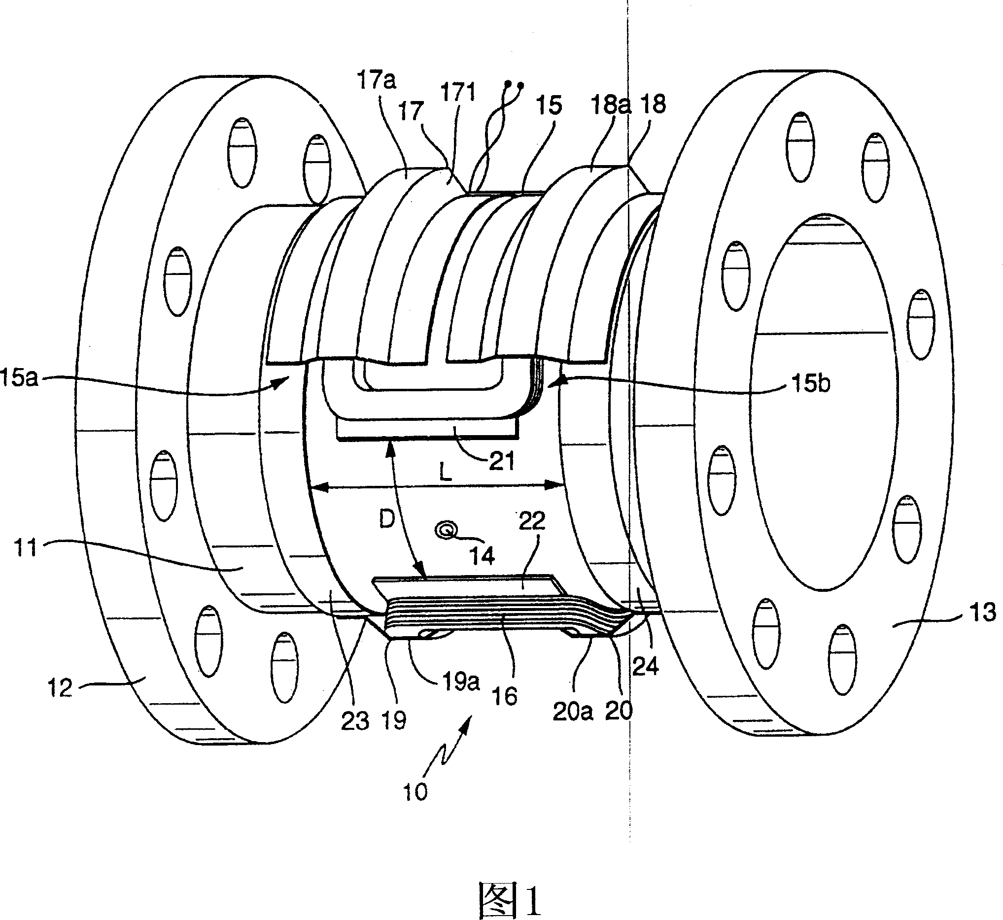
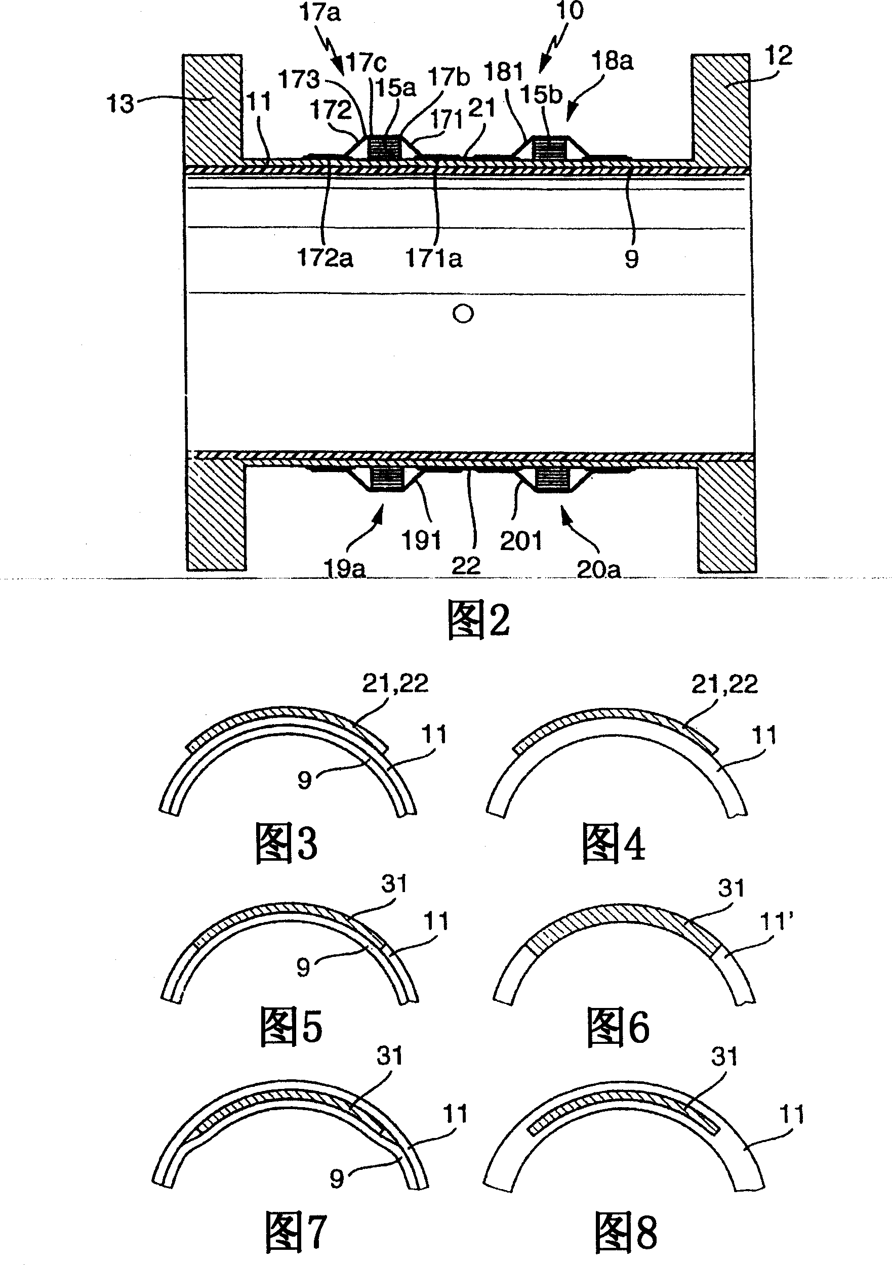
[0031] The magnetically inductive flow sensor 10 shown schematically in Figures 1 and 2 is particularly suitable for measuring conductive fluids flowing in pipes (not shown) having a nominal diameter in the range of approximately 200-700 mm, especially in the range of 350-600 mm. For guiding the fluid, the flow sensor has a measuring tube 11 which can be inserted into the pipeline. The measuring tube 11 can be made of a non-ferromagnetic material such as stainless steel, a suitable c...
PUM
Abstract
The invention relates to a flow rate sensor (10), which is designed to measure an electrically conductive fluid that flows in pipework. Said sensor comprises a measuring tube (11), which can be inserted into the run of pipework to conduct the fluid, said measuring tube (11) being electrically non-conductive on at least one inner face that comes into contact with the fluid, an electrode assembly (14) comprising at least two measuring electrodes that are located on the measuring tube and tap an electric voltage that is induced in the fluid, in addition to a magnetic field system that is also located on the measuring tube (11). The magnetic field system of the inventive flow rate sensor is equipped with at least two saddle-shaped field coils (15, 16), for generating a magnetic field that penetrates the fluid when operational, a respective ferromagnetic pole shoe (21, 22) for the field coils, for conducting the magnetic field towards the fluid and at least one ferromagnetic feedback element running around the measuring tube upstream of the two field coils and at least one ferromagnetic feedback element (23, 24) running around the measuring tube downstream of the two field coils, for conducting the magnetic field around said measuring tube. The pole shoes are magnetically coupled to the feedback elements by means of respective ferromagnetic coupling elements (17, 18, 19, 20). Each of said coupling elements, which are preferably configured in a standard manner, comprises at least one substantially gully-type cover segment (17a, 18a, 19a, 20a), which receives a first winding section of the respective field coil, said section essentially lying on a first circumferential segment of the measuring tube, or a second winding section (15a, 15b) of the respective field coil, said section essentially lying on a second circumferential segment of the measuring tube.
Description
technical field [0001] The invention relates to a magnetic induction flow sensor comprising a measuring tube through which a conductive fluid to be measured flows and a saddle coil for generating a magnetic field cutting the fluid. Background technique [0002] For purposes of describing the present invention, "flow sensor" refers to the substantially mechanical portion of a magnetic inductive flow meter without coil current generating circuitry. Such magnetic inductive flow sensors are known to use Faraday's law of induction to generate a measurement voltage. [0003] Various embodiments of magnetically inductive flow sensors for measuring electrically conductive fluids flowing in pipelines are disclosed in DE-A 20 40 682, US-A 46 41 537, US-A 47 74 844 or WO-A91 / 11731. Each flow sensor shown includes: [0004] - measuring tubes, installed in pipes for conducting fluids, the measuring tubes being electrically non-conductive at least on the inner surface in contact with th...
Claims
Application Information
Patent Timeline
Application Date:The date an application was filed.
Publication Date:The date a patent or application was officially published.
First Publication Date:The earliest publication date of a patent with the same application number.
Issue Date:Publication date of the patent grant document.
PCT Entry Date:The Entry date of PCT National Phase.
Estimated Expiry Date:The statutory expiry date of a patent right according to the Patent Law, and it is the longest term of protection that the patent right can achieve without the termination of the patent right due to other reasons(Term extension factor has been taken into account ).
Invalid Date:Actual expiry date is based on effective date or publication date of legal transaction data of invalid patent.