Automatic regulating device for gas induction error

An automatic adjustment device and gas technology, applied in the direction of gas/liquid distribution and storage, pipeline system, mechanical equipment, etc., can solve the problems of error adjustment limit, change, sensor characteristic value change, etc.

Inactive Publication Date: 2007-06-06
崔荣桓
View PDF0 Cites 3 Cited by
  • Summary
  • Abstract
  • Description
  • Claims
  • Application Information

AI Technical Summary

Problems solved by technology

[0007] However, in order to safely sense gas in this existing gas sensing device, the staff directly adjusts the sensing error of the output signal of the gas sensor installed in the chamber filled with a certain

Method used


Image

  • Automatic regulating device for gas induction error
  • Automatic regulating device for gas induction error
  • Automatic regulating device for gas induction error

Examples


Embodiment Construction

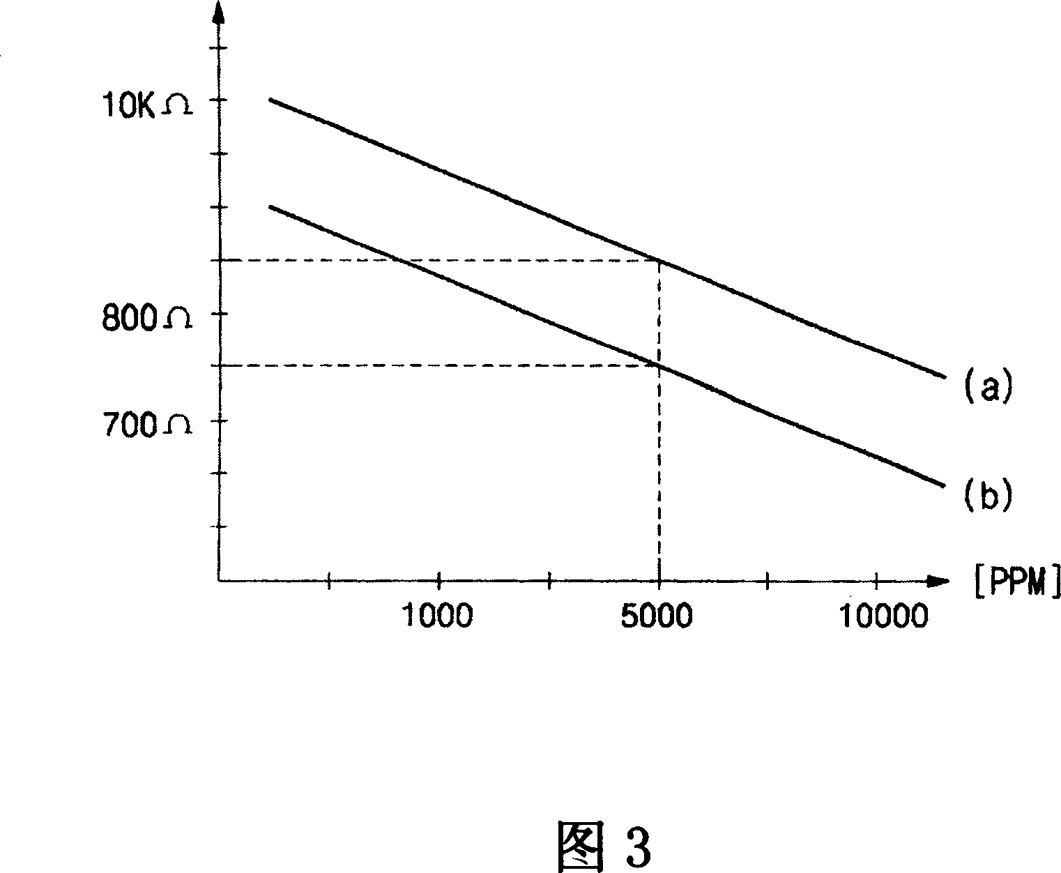
[0019] FIG. 2 is a block diagram of an automatic error adjustment device for a gas sensor of a gas sensing device according to an embodiment of the present invention, and FIG. 3 is a graph showing measurement for setting an existing error value of a gas sensor.

[0020] The present invention relates to a device capable of automatically adjusting the error caused by the inherent resistance value of a gas sensor of a gas sensing device. As shown in Figure 2 and Figure 3, the device is connected with: a gas sensing part 10, connected with a gas sensor for sensing gas; a temperature sensing part 20, connected with a temperature sensor; a storage part 30, connected with a stored gas sensor The memory device of the standard value and the error value; the input unit 50 can select the input condition mode required for adjusting the induction error of the gas sensor; the setting control unit 40 is used to input the gas sensing unit 10, the temperature sensing unit 20, the storage unit ...


PUM


Abstract

The invention relates to a gas induction error automatic control device, in which a gas sensor for the gas inductor is put in a chamber with a certain gas concentration and the measured value taken as the proper error value of the gas sensor is stored in the storage part. A set control part can automatically set the proper resistance quantity of the gas sensor.

Description

technical field [0001] The present invention relates to an automatic adjustment device for gas induction error, in particular to a method for placing a gas sensor used for a gas sensor in a chamber with a certain gas concentration, and regarding the measured value as the inherent error of the gas sensor The value is stored in the storage unit, and the setting control unit (40) automatically sets the gas sensing error automatic adjustment device of the intrinsic resistance value of the gas sensor. Background technique [0002] Generally, gas (GAS) is supplied to gas appliances such as boilers or gas stoves through pipes, and a certain amount of gas. This kind of gas is easy to leak through the cracks of the pipeline and cause a fire, or the toxic gas after burning flows into the outdoor or indoor, which constitutes a safety hazard of toxic gas. [0003] With the devices that use natural gas (LNG) and propane gas (LPG) as fuel, the gap gas passing through the pipes is leaked ...

Claims


Application Information

Patent Timeline
IPC IPC(8): F17D5/06
Inventor 崔荣桓
Owner 崔荣桓
Why Eureka
Try Eureka