LED lighting tube for fluorescent lamp device

A technology of LED lighting tubes and fluorescent lamps, which is applied in the fields of energy technology and environmental protection technology, can solve the problems of difficulty and difficulty in application, and achieve the effect of improving efficacy

Inactive Publication Date: 2007-06-06
YASHIMA DENGYO
View PDF1 Cites 13 Cited by
  • Summary
  • Abstract
  • Description
  • Claims
  • Application Information

AI Technical Summary

Problems solved by technology

However, it is difficult to solve the following problems, so it is considered that it is difficult to apply

Method used


Image

  • LED lighting tube for fluorescent lamp device
  • LED lighting tube for fluorescent lamp device
  • LED lighting tube for fluorescent lamp device

Examples


Embodiment Construction

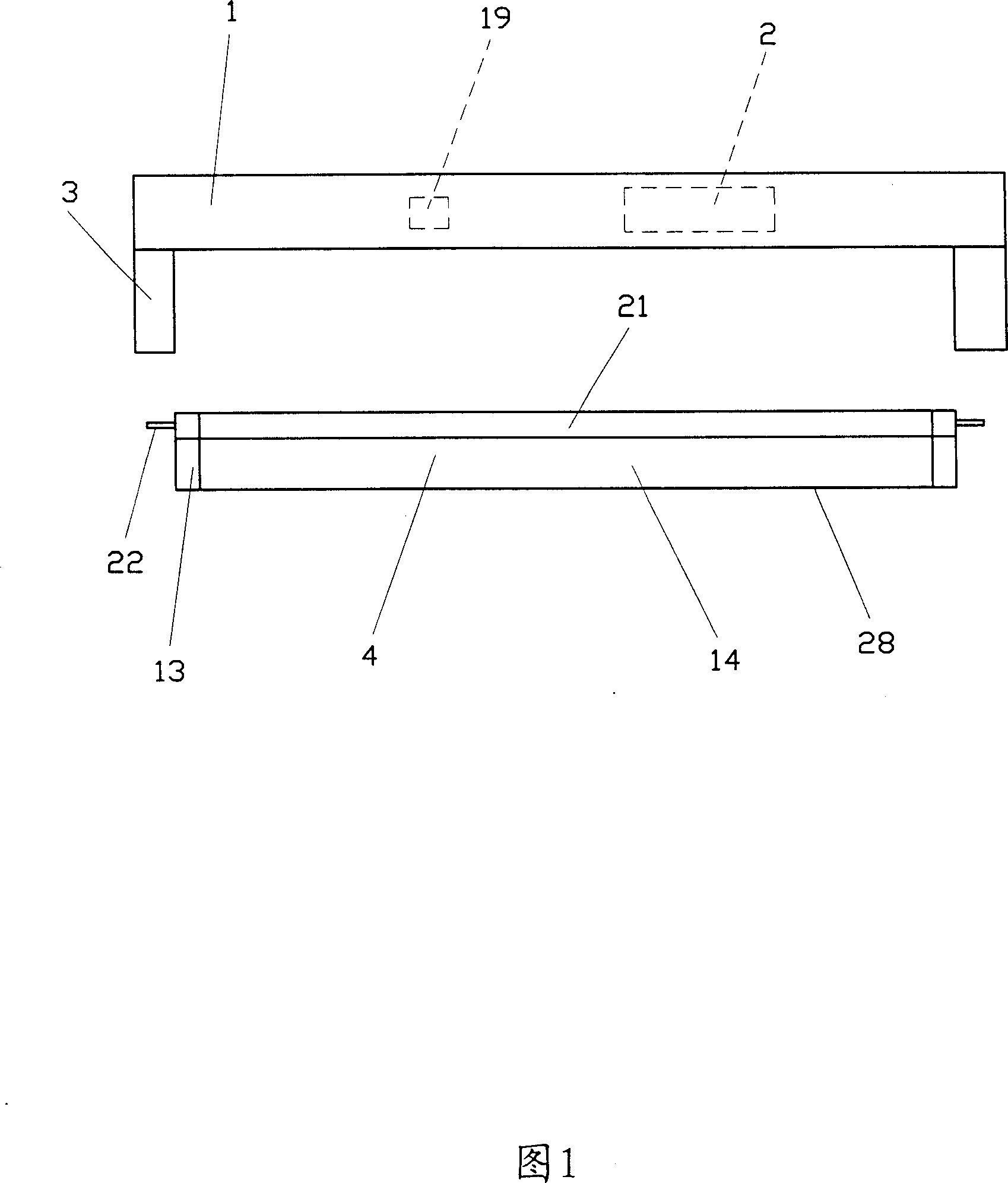
[0034] First, please refer to FIG. 1 , the present invention installs a voltage stabilizer 2 and a fluorescent lamp 19 in an existing fluorescent lamp device 1 , as well as an installation part 3 for assembling a lighting tube. The LED lighting tube 4 can be made with the same size as the existing fluorescent lamp, and has a metal cover 13 and a terminal 22 at the end of the tube portion 14, and can be installed on the mounting portion 3 of the fluorescent lamp device 1.

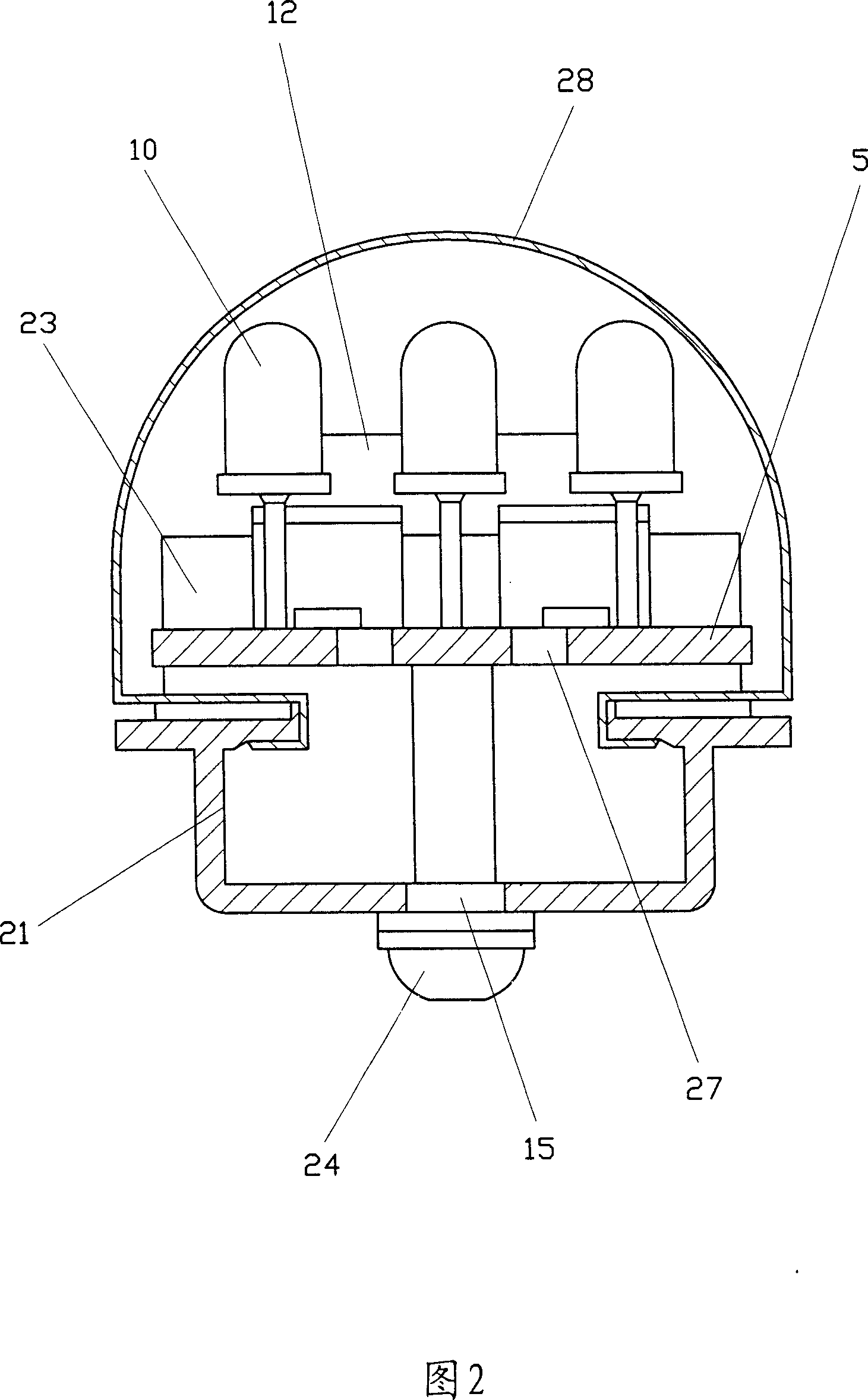
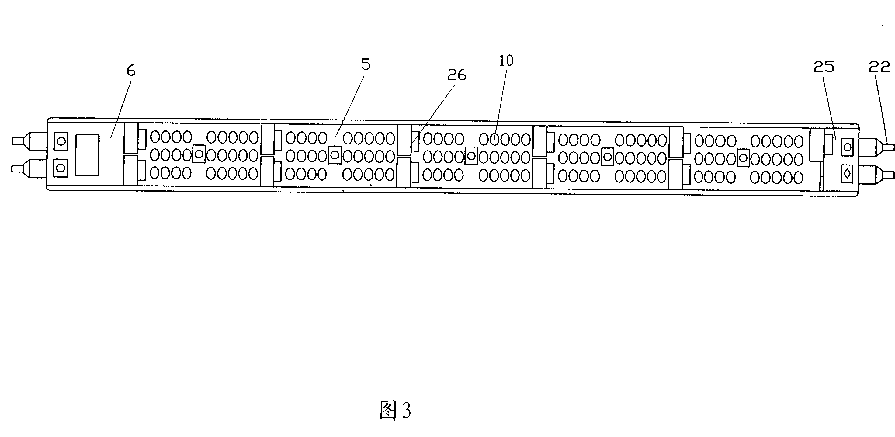
[0035] As shown in FIG. 2 , it is a cross-sectional view of the LED lighting tube 4 (please refer to FIG. 1 ). The LED lighting tube 4 is based on a rail 21 made of metal or molded products, on which a protective cover 28 made of a light-transmitting material is covered. The protective cover 28 is rolled into the inner side of the upper part of the rail 21 and installed, and is tightly installed with the rail 21 . Inside the LED lighting tube 4 , several LED substrates 5 , power supply substrates 6 and meta...


PUM


Abstract

A light emitting diode (LED) lighting unit applied to a fluorescent lighting fixture including a light emitting diode (LED) lighting unit mounted in an existing fluorescent lighting fixture; a source part being disposed in the LED lighting unit; polarity being switched by means of the source part installed in the LED lighting unit depending on the direction of the installation direction of the LED lighting unit; the LED lighting unit being capable of coping with changed polarity resulted from any direction of the installation; a first bridge rectifier and a second bridge rectifier installed in the LED lighting unit functioning to rectify the current supplied from a ballast of the fluorescent lighting fixture and to conduct a light emitting diode (LED) assembled unit connected in series and parallel.

Description

technical field [0001] The invention relates to an LED lighting tube used in fluorescent lamp equipment, especially refers to the fact that the LED lighting tube can be used to replace the fluorescent lamp tube in general and widely used fluorescent lamp equipment, and also relates to energy technology and environmental protection technology. Background technique [0002] Fluorescent tubes are widely used because they have the advantages of longer life and lower power consumption than incandescent lamps. However, while the energy problem has become more serious, the problem of environmental pollution caused by mercury spilled from fluorescent tubes that have been discarded after use has arisen. For this reason, can replace fluorescent tube and use the conception of LED, just be launched like this in the No. 63-121461 of Japanese Open Application Patent Publication. Furthermore, as disclosed in Japanese Patent Publication No. Hei 06-54103, it is also possible to design LED l...

Claims


Application Information

Patent Timeline
Patent Type & Authority Applications(China)
IPC IPC(8): H05B35/00F21V29/02F21V23/00F21Y113/02F21V23/02F21V29/00F21Y113/20H01L33/50
CPCH05B33/0818H05B33/0887F21K9/00F21Y2103/003F21K9/17F21Y2101/02Y02B20/348Y02B20/386H05B33/0803H05B33/0809F21V23/02F21V23/06F21V29/677F21K9/27F21Y2103/10F21Y2115/10Y02B20/30H05B45/345H05B45/3578H05B45/00
Inventor 杉英一桥爪贤治郎
Owner YASHIMA DENGYO
Why Eureka
Try Eureka