Rotation control device, rotation control method, and construction machine

A technology of rotating control device and rotating body, applied in mechanical equipment, engine control, construction, etc., can solve problems such as incongruity and decrease in rotation speed

Inactive Publication Date: 2007-06-06
KOMATSU LTD
View PDF1 Cites 2 Cited by
  • Summary
  • Abstract
  • Description
  • Claims
  • Application Information

AI Technical Summary

Problems solved by technology

This is because the working oil used to rotate the rotating body is also used to drive the work machine, so that the rotation speed decreases
I

Method used


Image

  • Rotation control device, rotation control method, and construction machine
  • Rotation control device, rotation control method, and construction machine
  • Rotation control device, rotation control method, and construction machine

Examples


no. 1 approach

[0030] [1-1] Overall structure

[0031] Hereinafter, a first embodiment of the present invention will be described based on the drawings.

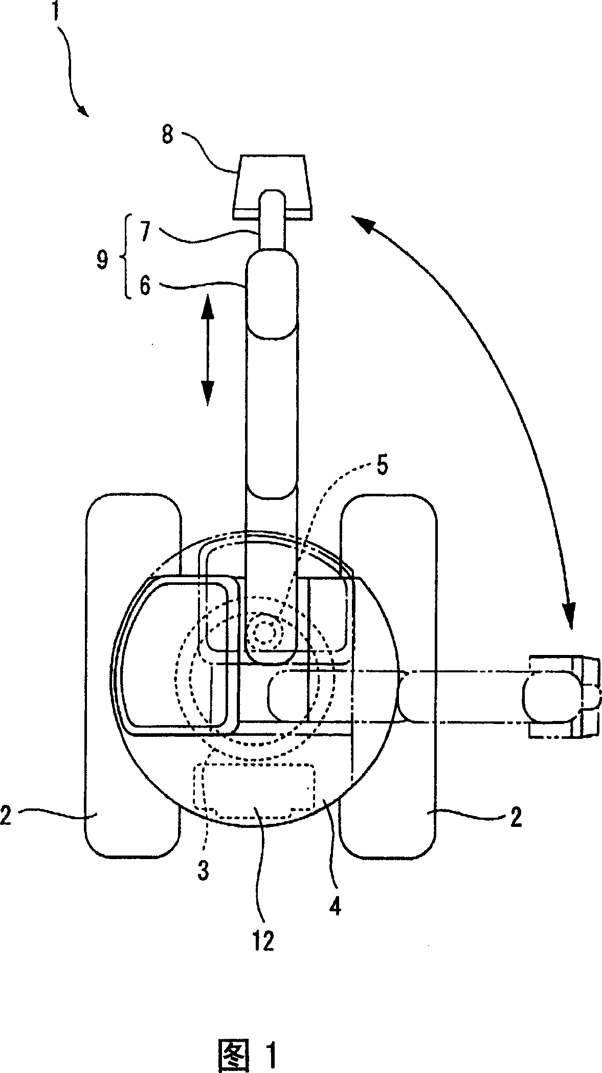
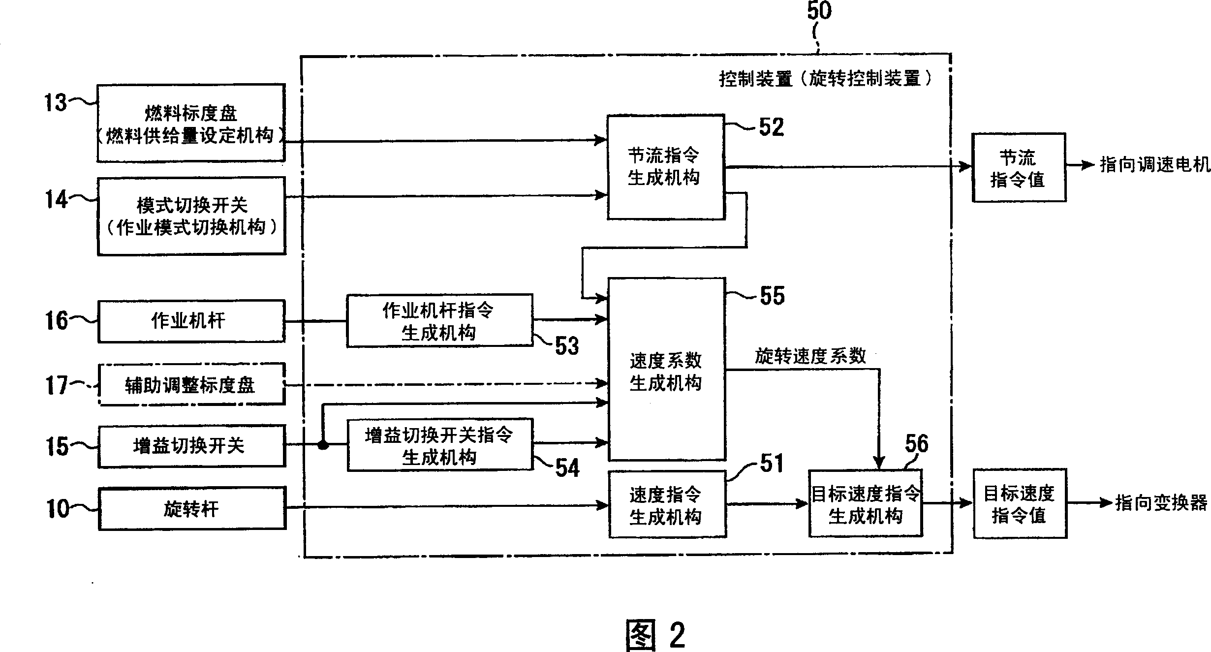
[0032] FIG. 1 is a plan view showing an electric rotary excavator (construction machine) according to this embodiment, and FIG. 2 is a block diagram illustrating a control device (rotation control device) 50 mounted on the electric rotary excavator 1 .

[0033] In FIG. 1 , an electric rotary single-bucket excavator 1 has a rotating body 4 which is provided on a truck frame constituting a lower moving body 2 via a swing circle 3 , and which is engaged with the swing circle 3 . The electric motor 5 rotationally drives the rotating body 4 . The electric power source of the electric motor 5 is an unillustrated generator mounted on the rotating body 4 , and the generator is driven by an engine 12 .

[0034] A boom 6 , an arm 7 , and a bucket 8 each driven by a hydraulic cylinder (not shown) are provided on the revolving body 4 , and these con...


PUM


Abstract

A control device (50) for an electrically rotated shovel, in which a rotation speed factor is created according the condition set by a fuel dial (13) or the condition selected by a mode change switch (14), and the magnitude of a target speed command value is varied to vary the rotation speed of a rotating body (4). As a result, when the speed of an engine is reduced by operation of the fuel dial (13) or the mode change switch (14), the rotation speed of the rotating body (4) can be reduced accordingly, and when the engine speed is increased, the rotation speed can be increased. This can provide drive comfort almost similar to that obtained when the rotating body (4) is rotated by an ordinary hydraulic system. As a consequence, even if a user changes a shovel from a conventional hydraulic shovel to this electrically rotated shovel, the user does not have a strange feeling.

Description

technical field [0001] The present invention relates to a rotation control device, a rotation control method, and a construction machine of a rotating body that is rotated by an electric motor. Background technique [0002] In recent years, a hybrid type electric rotary shovel in which an electric motor is used to drive a rotating body and a hydraulic transmission is used to drive a working machine or a moving body has been developed (for example, refer to Patent Document 1). [0003] In such an electric rotary bucket excavator, since the revolving body is rotated by the electric motor, even if the revolving body is rotated simultaneously with the lifting operation of the hydraulically driven boom or arm, The motion of the rotating body does not affect the lifting motion of the boom or the arm. Therefore, compared with a general hydraulic single-bucket excavator that also hydraulically drives the revolving body, the loss in the control valve and the like can be reduced, and...

Claims


Application Information

Patent Timeline
IPC IPC(8): E02F9/20F02D29/00E02F9/22
CPCE02F9/2025E02F9/123E02F9/20F02D29/00
Inventor 森永淳井上宏昭
Owner KOMATSU LTD
Why Eureka
Try Eureka