Heavyoil catalytic cracking and gasoline modifying mutual control method and apparatus

A heavy oil catalysis and upgrading technology, applied in the catalytic conversion process, the device for realizing the process, and the field of the catalytic conversion process of petroleum hydrocarbons, which can solve the problem of the decrease of the yield of light oil, the increase of the yield of cracked gas, the over-cracking reaction of oil and gas, etc. question

Active Publication Date: 2007-06-13
BEIJING YANSHAN YULONG PEC
View PDF3 Cites 8 Cited by
  • Summary
  • Abstract
  • Description
  • Claims
  • Application Information

AI Technical Summary

Problems solved by technology

However, these technologies also have the following deficiencies: firstly, the catalyst in the gasoline reforming catalyst and the catalyst in the heavy oil riser have different activities and temperatures, and it takes a certain amount of time for the two to mix uniformly in the heavy oil riser reactor. The inhomogeneity of local catalyst density, activity and temperature in the riser reactor will aggravate the local overcracking and thermal cracking reactions of oil and gas in the ris

Method used


Image

  • Heavyoil catalytic cracking and gasoline modifying mutual control method and apparatus
  • Heavyoil catalytic cracking and gasoline modifying mutual control method and apparatus
  • Heavyoil catalytic cracking and gasoline modifying mutual control method and apparatus

Examples


Embodiment 1

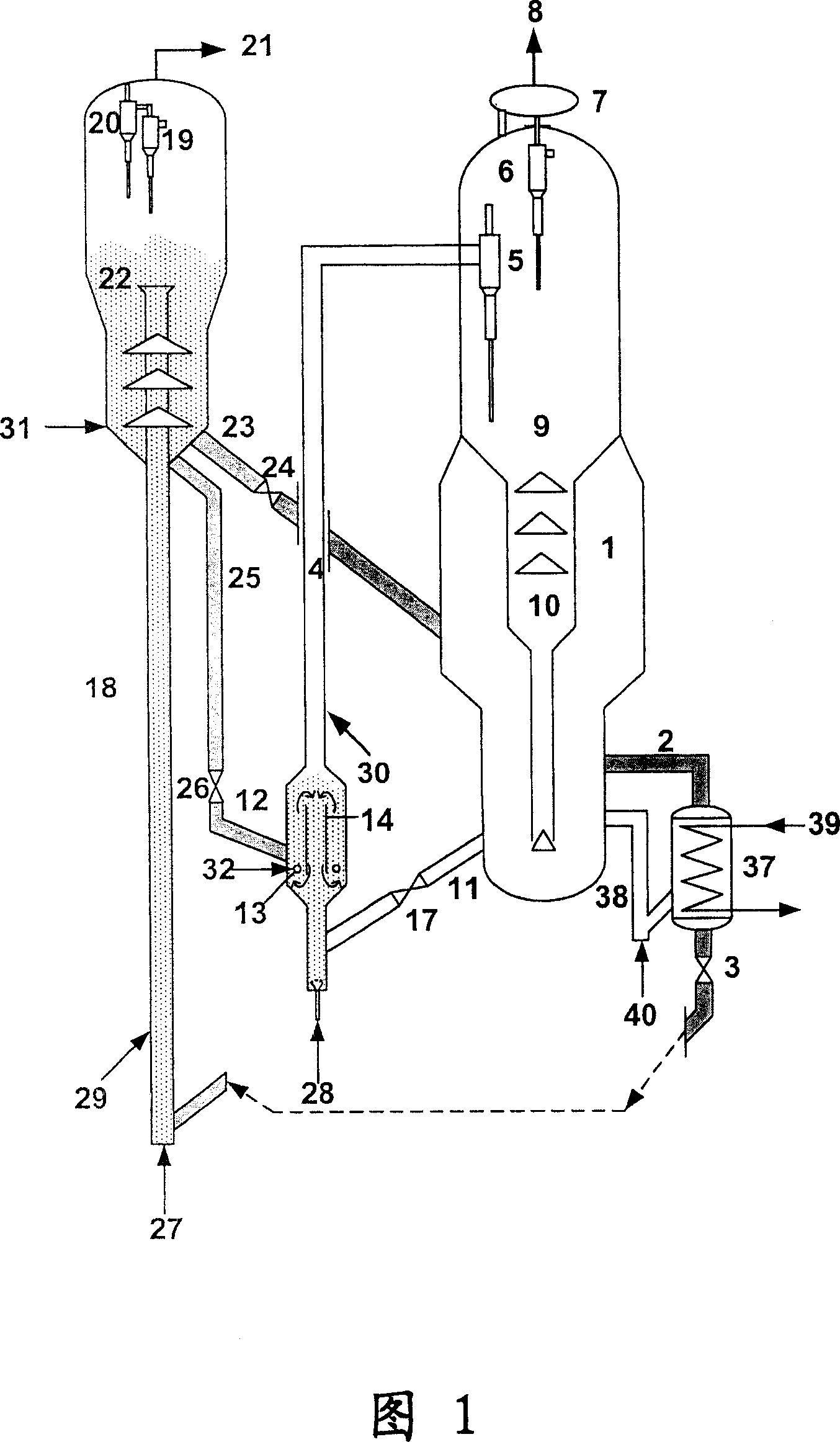
[0065] The process flow is shown in Figure 1: a catalyst circulation mixer 12 is set up at the bottom of the industrial catalytic cracking unit heavy oil riser reactor 4 with catalytic gasoline upgrading auxiliary fluidization reactor, and the top and bottom of the catalyst circulation mixer 12 are connected with The heavy oil riser reactors are connected to each other. Catalyst circulation mixer 12 is a cylindrical cylinder, inside coaxially arranges an inner cylinder 14, forms outer annular space between inner and outer cylinders, and a gas outer ring distribution pipe 13 is arranged at the bottom of this annular space, and water vapor 32 enters the annular space in the catalyst circulation mixer 12 through the gas outer ring distribution pipe 13 as a fluidization medium, and adjusts the flow rate of the water vapor 32 entering the catalyst circulation mixer 12 so that the gas velocity in the outer ring space of the catalyst circulation mixer 12 is low Due to the gas velocit...

Embodiment 2

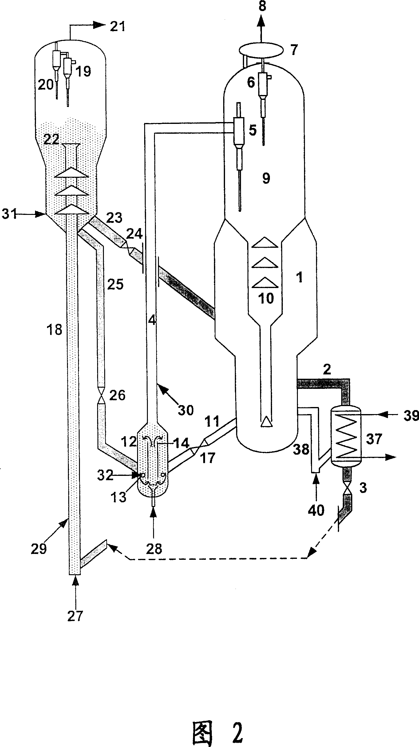
[0070] Referring to the flow process shown in Figure 2, it is briefly described as follows: a catalyst loop mixer 12 is set up at the bottom of the heavy oil riser reactor 4 of the industrial catalytic cracking unit with catalytic gasoline upgrading auxiliary fluidization reactor, and the catalyst loop mixer 12 The top of the reactor is connected with the heavy oil riser reactor 4, and the bottom of the catalyst circulation mixer 12 is a closed head. The catalyst circulation mixer 12 is a cylindrical cylinder, and an inner cylinder 14 is arranged inside. An outer ring space is formed between the inner cylinder 14 and the outer wall of the catalyst circulation mixer 12, and a gas outer ring distribution pipe is arranged at the bottom of the ring space. 13. The water vapor 32 enters the outer ring space of the catalyst circulation mixer 12 through the gas outer ring distribution pipe 13, and the pre-lift steam 28 at the bottom of the original heavy oil riser reactor 4 enters the ...

Embodiment 3

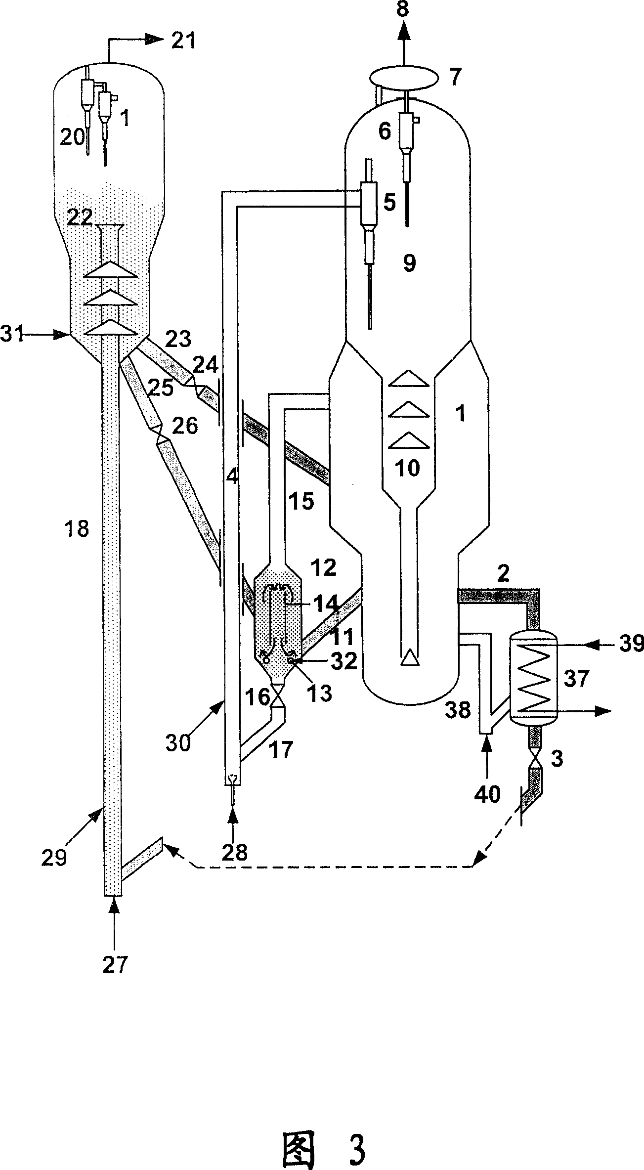
[0075]Referring to the flow process shown in Figure 3, it is briefly described as follows: a catalyst circulation mixer 12 is set up next to the industrial catalytic cracking unit heavy oil riser reactor 4 with catalytic gasoline upgrading auxiliary fluidization reactor, and the catalyst circulation mixer 12 The top of the catalyst loop mixer 12 is connected with the fourth regenerated catalyst delivery pipe 15, and the bottom of the catalyst circulation mixer 12 is connected with the mixed catalyst delivery pipe 16. The catalyst circulation mixer 12 is a cylindrical cylinder, and an inner cylinder 14 is arranged inside. An outer ring space is formed between the inner cylinder 14 and the outer wall of the catalyst circulation mixer 12, and a gas outer ring distribution pipe is arranged at the bottom of the ring space. 13. Water vapor 32 enters the outer ring space in the catalyst circulation mixer 12 through the gas outer ring distribution pipe 13, so that the gas velocity in t...


PUM


Abstract

The invention relates to the method and the device to adjust and control in heavy oil catalytic cracking and gasoline modified process. It adds the catalyst circular mixer and the regenerative catalyst cooler into the heavy oil catalytic cracking system with the gasoline modified assistant fluidized reactor. So it can lead the future and regenerative catalyst from the gasoline modified assistant fluidized reactor to the mixer and mix uniformly in the water vapour, then the mixture go into the heavy oil reactor riser to crack with the raw oil; the regenerative catalyst used for the gasoline modified is cooled in cooler before going into the assistant fluidized reactor and reacts with the vapour gasoline material. The invention can decrease the gasoline alkene content to 18%(V) and it is proper for the country environment protecting rule but improve the yield of the light oil.

Description

technical field [0001] The invention relates to a catalytic conversion process of petroleum hydrocarbons, in particular to a coupling technology of a catalytic conversion process for reducing olefin content through heavy oil catalytic cracking conversion and catalytic gasoline modification and a device for realizing the process, belonging to the field of petrochemical technology. Background technique [0002] In recent years, with the increasingly stringent environmental protection standards, new gasoline standards have been issued at home and abroad, which put forward strict requirements on the olefin content and sulfur content in gasoline. In China, the new gasoline and diesel standards began to be implemented on July 1, 2003. The olefin content of gasoline is ≯35% (v), and the sulfur content is ≯800ppm; the implementation standard on July 1, 2005 requires gasoline sulfur content≯500ppm; 2007 In 2009, gasoline quality standards in some areas were required to meet Euro III ...

Claims


Application Information

Patent Timeline
IPC IPC(8): C10G55/06C10G11/16C10G7/00
Inventor 王刚高金森徐春明卢春喜
Owner BEIJING YANSHAN YULONG PEC
Why Eureka
Try Eureka