Exposure equipment

An exposure device and an exposed technology are applied in the direction of exposure devices, optics, instruments, etc. in the photoplate making process, which can solve the problems of increased adjustment time, long exposure time, and prolonged exposure light irradiation time, so as to reduce dirt or damage, Improved exposure accuracy and consistent exposure position

Active Publication Date: 2007-06-13
V TECH CO LTD
View PDF1 Cites 6 Cited by
  • Summary
  • Abstract
  • Description
  • Claims
  • Application Information

AI Technical Summary

Problems solved by technology

[0004] However, in such a conventional exposure apparatus, when the exposure to a predetermined area is completed, the exposure operation is temporarily stopped, and the light shielding plate is relatively step-moved with respect to the substrate, and the positional alignment and gap adjustment between the substrate and the light shielding plate are performed again. After exposure, it takes time to perform position alignment and gap adjustment multiple times, and it takes a long time for exposure
[0005] Also, the conventional exposure apparatus can use a small-area light-shielding plate to expose a predetermined pattern on the entire surface of a large substrate. Therefore, it has the advantage of reducing the cost of the light-shielding plate used, but it also has the following problems: the light-shielding plate The smaller the area, the more times the position alignment and gap adjustments will be, and the adjustment time will increase correspondingly, so that the exposure time will be longer
[0006] In addition, in order to shorten the time for alignment and gap adjustment, when a large light shield is used to a certain extent, a large amount of energy is required for the exposure light, and since the power of the light source is limited, it is necessary to lengthen the irradiation time of the exposure light. As a result, the exposure time cannot be shortened either.

Method used


Image

  • Exposure equipment
  • Exposure equipment
  • Exposure equipment

Examples


Embodiment Construction

[0037] Embodiments of the present invention will be described in detail below with reference to the drawings.

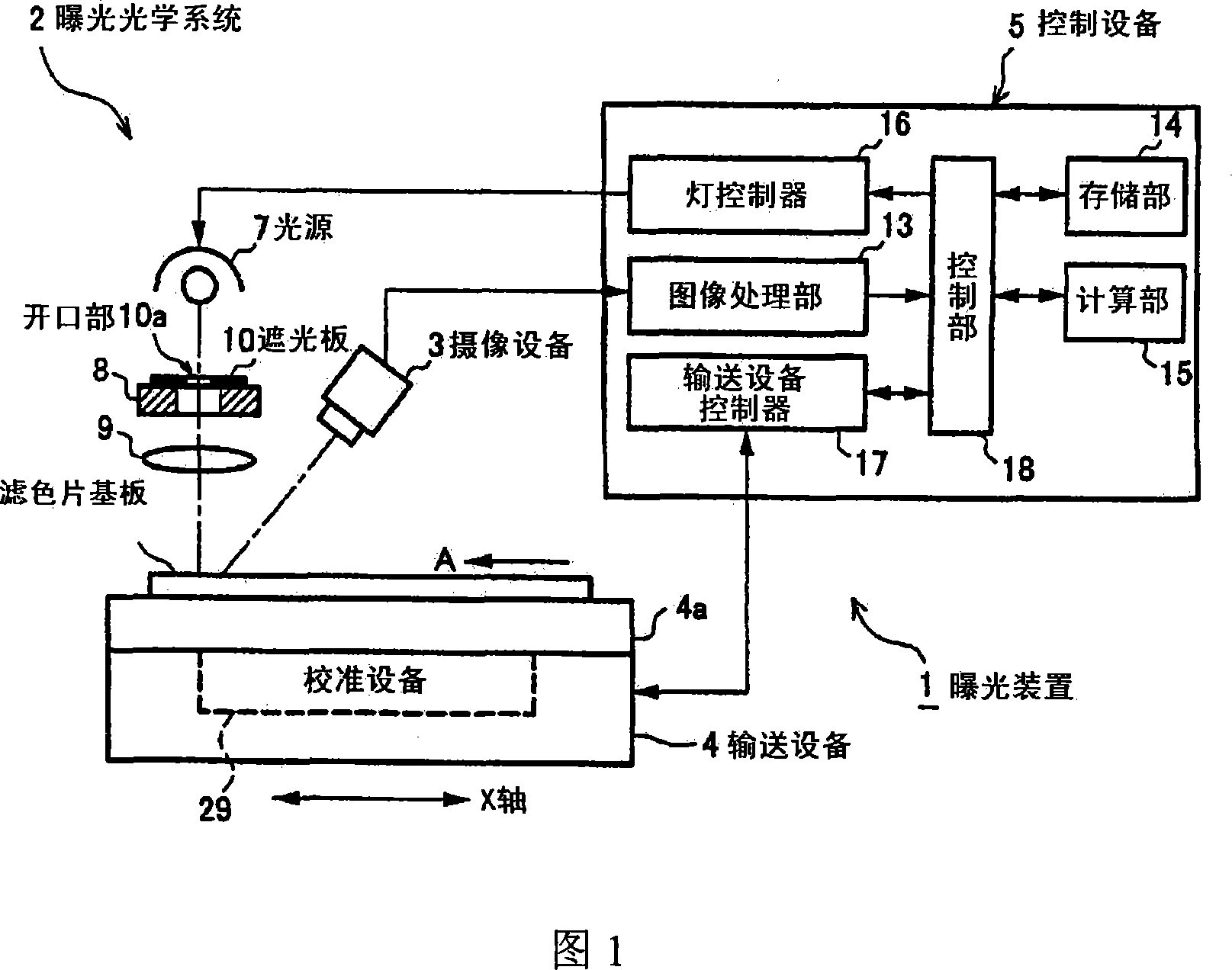
[0038] FIG. 1 is a schematic diagram showing a first embodiment of the exposure apparatus of the present invention. This exposure apparatus 1 irradiates exposure light with an exposure optical system to expose an image of an opening of a light-shielding plate interposed in the path of the exposure optical system on an object to be exposed, and therefore includes an exposure optical system 2 and an imaging device 3 , conveying equipment 4, control equipment 5. In addition, the color filter substrate of a liquid crystal display unit is demonstrated as an example of an object to be exposed.

[0039] The exposure optical system 2 irradiates exposure light onto the color filter substrate 6 coated with a photosensitive agent to expose a predetermined color filter pattern, and includes a light source 7 , a light shield stage 8 and an imaging lens 9 .

[0040] The light so...


PUM


Abstract

Exposure equipment (1) is provided with an exposure optical system (2) for irradiating a color filter board (6) with exposure light from a light source (7), and a transfer means (4), on which the color filter board (6) arranged to face the exposure optical system (2) is placed to be transferred at a fixed speed. The exposure equipment exposes an image on an opening part (10a) of a mask (10) arranged on an optical path of the exposure optical system (2). The exposure equipment is provided with an image pickup means (3), which performs image pickup of a black matrix (11) previously formed on the color filter board (6), having the front side of an exposure position of the exposure optical system (2) in a shifting direction of the transfer means (4) as an image pickup apposition. The equipment is also provided with a control means (5), which detects a previously set reference position in the black matrix (11) of which image has been picked up by the image picked up means (3), controls irradiation timing of the exposure light of the exposure optical system (2) with the reference position as the standard, and exposes the image of the opening part (10a) of the mask (10) at a prescribed position on the color filter board (6). Thus, the exposure equipment which performs efficient exposure to a large exposure area by using the small mask is provided.

Description

technical field [0001] The present invention relates to an exposure apparatus for exposing an image of an opening of a light-shielding plate interposed in a path of the exposure optical system on an object to be exposed by irradiating exposure light with an exposure optical system, and more specifically relates to an exposure apparatus as follows : By moving the object to be exposed at a certain speed, and at the same time taking the preset reference position of the reference pattern formed on the object to be exposed as a reference, the setting of the exposure position and the irradiation time of the exposure light are controlled. to efficiently expose over a wide exposure area. Background technique [0002] Existing exposure devices of this kind include: a stage, which holds the substrate with the photosensitive material facing upwards and can control the movement of the substrate in the X, Y, Z axial and θ directions, and can at least move the substrate in the X, Y Stepp...

Claims


Application Information

Patent Timeline
Patent Type & Authority Applications(China)
IPC IPC(8): G03F9/00
CPCG03F9/7088G03F7/20
Inventor 伊藤三好
Owner V TECH CO LTD
Why Eureka
Try Eureka