
Inspection fixture for printed wiring board

A technology for printed wiring boards and fixtures, applied in the directions of measurement leads/probes, measurement devices, instruments, etc., can solve problems such as insufficient response and increase in the outer diameter of the probe needle, and achieve easy exchange and stability. The effect of support

Inactive Publication Date: 2007-06-20
OHNISHI ELECTRONICS
View PDF1 Cites 2 Cited by
  • Summary
  • Abstract
  • Description
  • Claims
  • Application Information

AI Technical Summary

Problems solved by technology

[0004] However, in this inspection jig, since the inner sleeve 12 is arranged radially inward of the outer sleeve 10, and the coil spring 14 and the stylus 16 are accommodated radially inward of the inner sleeve 12, the The outer diameter of the probe body 8 has become larger, and there is a problem that it cannot fully cope with the fact that the actual assembly level of printed wiring board components is high in recent years.

Method used


Image

  • Inspection fixture for printed wiring board
  • Inspection fixture for printed wiring board
  • Inspection fixture for printed wiring board

Examples


Embodiment Construction

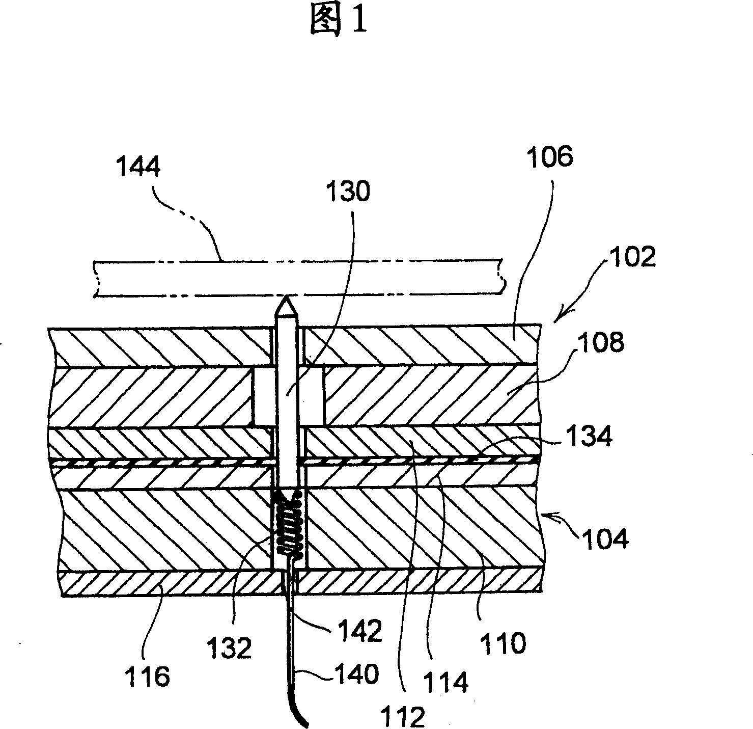
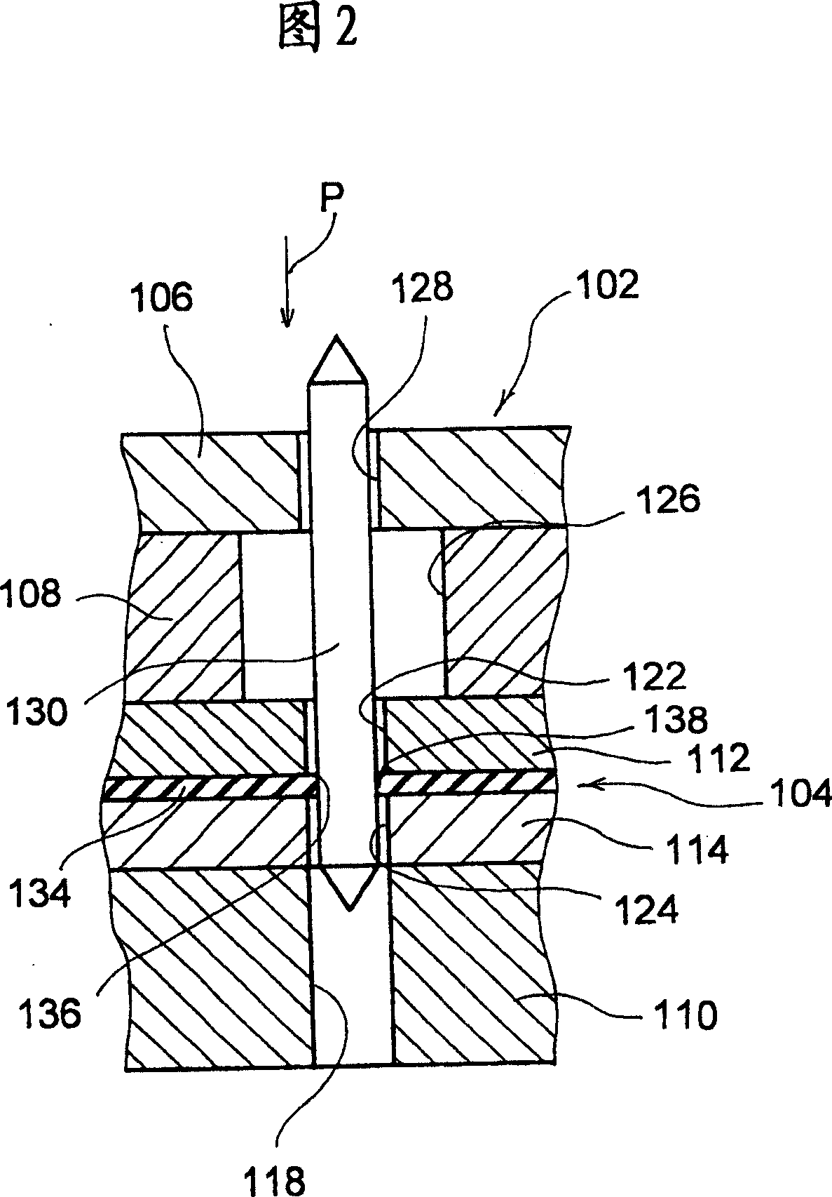
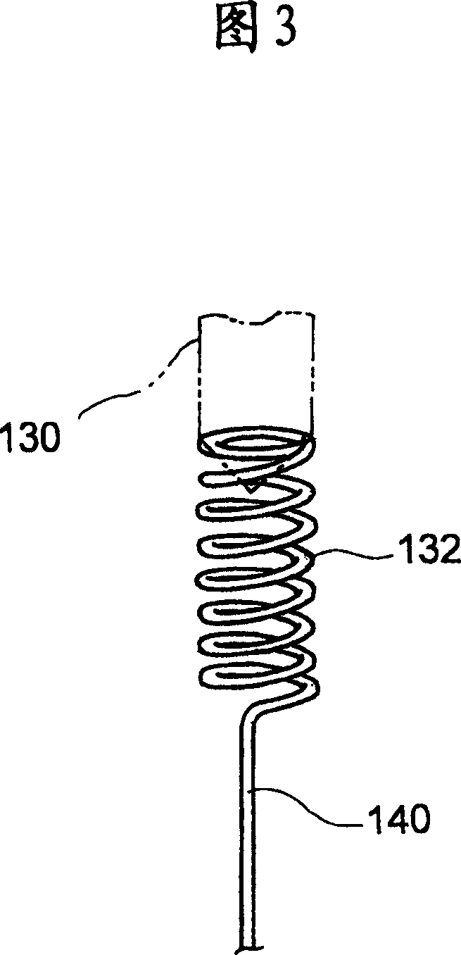
[0047] Hereinafter, the best embodiment of the printed wiring board inspection jig according to the present invention will be described with reference to FIGS. 1 to 5 . Fig. 1 is a sectional view showing an embodiment of the inspection fixture according to the present invention, Fig. 2 is an enlarged sectional view showing the main part of the inspection fixture in Fig. Front view of a magnified representation of a helical spring.

[0048] In FIGS. 1 and 2 , the inspection jig 102 shown in the figures includes a needle plate 104 , a protection plate 106 and a spacer plate 108 . The protection plate 106 is disposed on one side of the needle head plate 104 (the upper side in FIG. 1 and FIG. 2 ), and the isolation plate 108 is interposed between the needle head plate 104 and the protection plate 106 . These plates 104·106·108 are attached and fixed using, for example, nuts and bolts for fixing. In addition, the protective plate 106 and the isolation plate 108 are made of electron...


PUM


Abstract

Provided is an inspection fixture for printed wiring board capable of holding probe pins as desired, changing probe pins easily, and coping with requirement of high-density arrangement for printed wiring board. The inspection fixture for printed wiring board includes a pin board 104 having an accommodating hole 118 and installation holes 122, 124, a protection board 106 having a guiding hole 128, a probe pin 130 inserted into the installation holes 122, 124 of the pin board 104 with a front end thereof passing through the guiding hole 128 of the protection board 106 and protruding to the outside, and a spring member accommodated within the accommodating hole 118 of the pin board 104. The pin board 104 includes a rubber board 134, while a resilient holding portion 138 of the rubber board 134 resiliently holding a peripheral surface of the probe pin 138.

Description

technical field [0001] The present invention relates to a printed wiring board inspection jig used for inspecting a short circuit, an insulation state, and the like of a printed wiring board circuit. Background technique [0002] As well known, there is a structure shown in FIG. 6 as an inspection jig for inspecting printed wiring boards. This inspection jig includes a pinhead plate 2, a spacer plate 4 arranged on the front side of the pinhead plate 2, a protective plate 6 placed on the front side of the spacer plate 4, and a terminal of a printed wiring board to be inspected. The probe tip body 8 is connected electrically conductively, and the probe tip body 8 is mounted in the tip plate 2 . The stylus body 8 is composed of an outer sleeve 10 mounted on the needle plate 2 , an inner sleeve 12 arranged inside the outer sleeve 10 , and a coil spring accommodated in the inner sleeve 12 at the base side. 14. The stylus needle 16 is housed in the front end side of the inner ca...

Claims


Application Information

Patent Timeline
Patent Type & Authority Applications(China)
IPC IPC(8): G01R1/06G01R31/02
CPCG01R1/06722G01R1/07328
Inventor 中村慎七石川胜昭田中宏和
Owner OHNISHI ELECTRONICS
Learn More