Micro-driver, magnetic-head broken-wafer combination containing it and magnetic-disk driving unit

A technology of micro-drive and magnetic head, which is applied in driving/moving the recording head, aligning the magnetic track on the magnetic disk, maintaining the alignment of the head frame, etc. It can solve the problems of complex assembly process, limited manufacturing capacity or tolerance, complex processing and assembly process, etc.

Inactive Publication Date: 2007-06-20
SAE MAGNETICS (HK) LTD
View PDF0 Cites 2 Cited by
  • Summary
  • Abstract
  • Description
  • Claims
  • Application Information

AI Technical Summary

Problems solved by technology

In particular, the necks on both sides of the top plate of the micro-drive must have very high manufacturing accuracy. This is because the smaller the width of the necks 2048a, 2048b, the better the stroke amplitude performance, but the actual manufacturing capacity or tolerance limited, so the manufacturing quality of the critical dimension with high stroke performance is not easy to control. In addition, the width of the neck 2048a, 2048b is too small so that it may break when it is impacted, so its processing and assembly process is complicated and the cost is relatively high. Second, due to the inevitable inherent errors in the processing of the U-shaped frame of this micro-driver, the positions of the arms on both sides cannot be completely consistent, that is, the arms on both sides are not ideally symmetrical to each other. The piezoelectric sheets on the two arms are not ideally symmetrical to each other, so that when a voltage is applied to the piezoelectric sheets, the arms on both sides cannot deform with the same amplitude, so that the magnetic head installed between the two arms cannot achieve precise positioning. Position adjustment; in addition, when the piezoelectric micro-driver is excited, due to the limitation of the U-shaped frame of the micro-driver, the magnetic head will simply move in translation and cannot obtain a relatively large displacement; in addition, in the traditional technology, the The piezoelectric microactuator described above must physically bond the bottom plate of its U-shaped frame to the flexure of the cantilever with an adhesive such as epoxy glue, making the assembly process complex and costly

Method used


Image

  • Micro-driver, magnetic-head broken-wafer combination containing it and magnetic-disk driving unit
  • Micro-driver, magnetic-head broken-wafer combination containing it and magnetic-disk driving unit
  • Micro-driver, magnetic-head broken-wafer combination containing it and magnetic-disk driving unit

Examples


Embodiment Construction

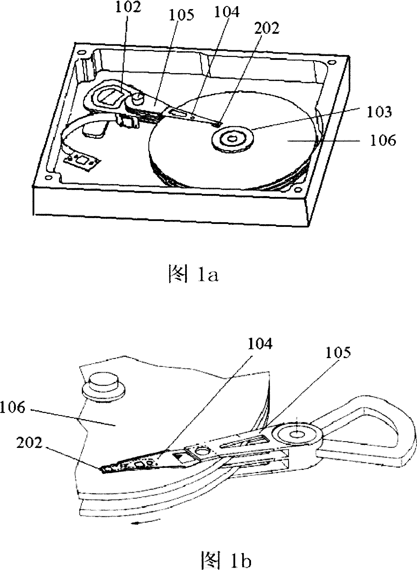
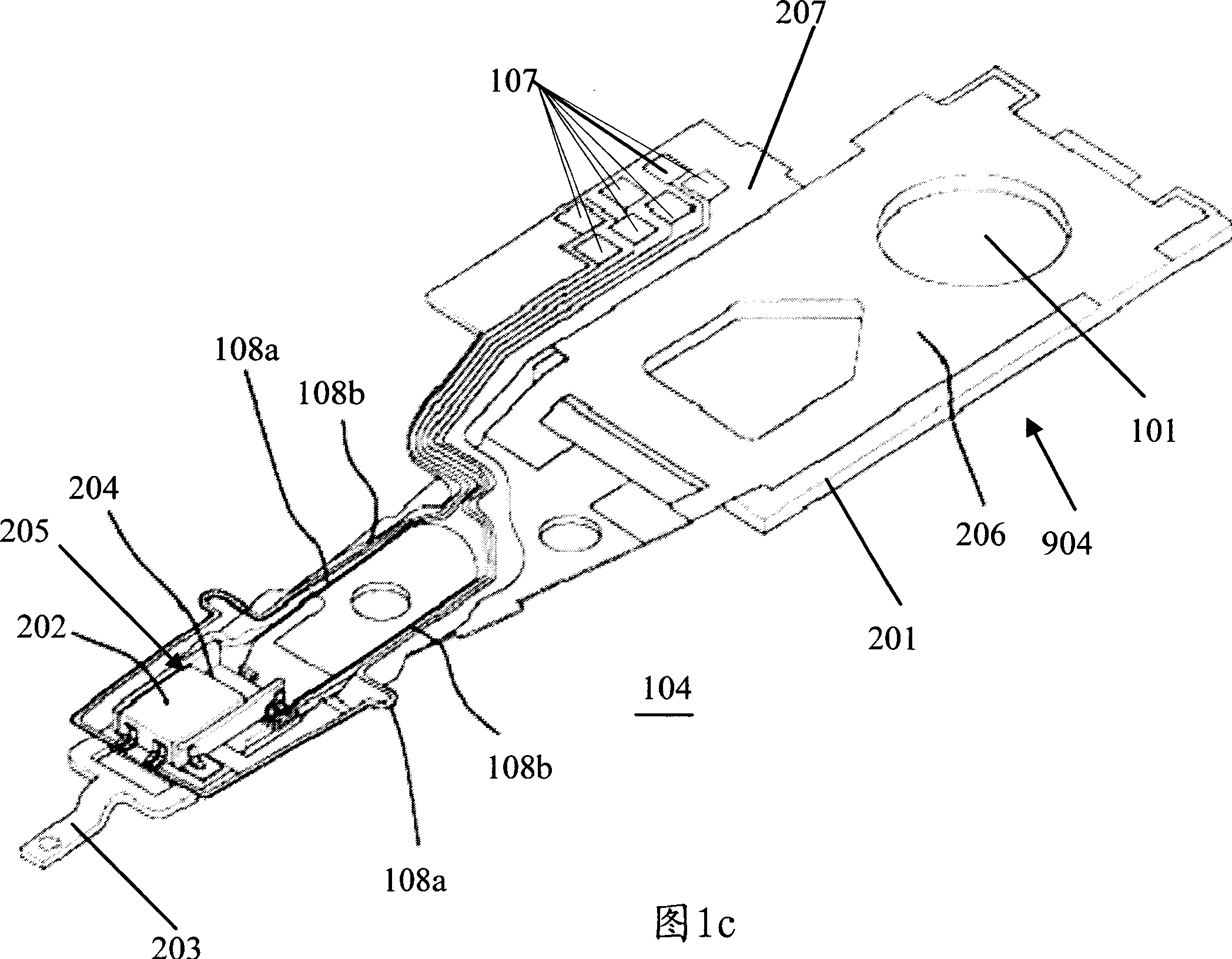
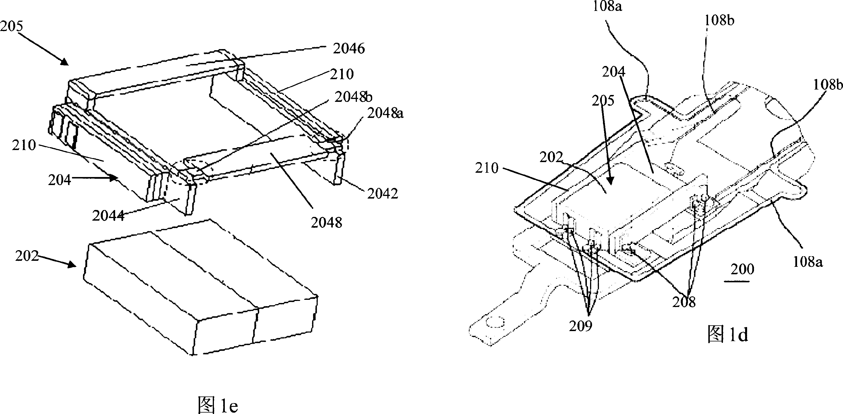
[0039] Several preferred embodiments of the present invention will now be described with reference to the drawings, in which like reference numerals represent like elements. As mentioned above, the present invention provides a micro-actuator for head gimbal assembly, including a support frame and at least one piezoelectric element; wherein the support frame includes a beam and a spacer provided at one end of the beam; the A piezoelectric element is mounted on the side of the beam; wherein the beam generates rotational motion when the piezoelectric element is excited. The micro-actuator of the present invention replaces the traditional U-shaped frame with a monolithic or beam-type frame, so that the piezoelectric element can be accurately installed on both sides of the monolithic frame in the form of back-to-back, thereby improving the piezoelectric element. position installation accuracy; secondly, the present invention installs the magnetic head at the end of the monolithic f...


PUM


Abstract

A micro-actuator used on magnetic head folding-plate assembly is prepared as forming support frame by a horizontal beam and interval body set at one end of said horizontal beam, arranging piezoelectric element at side of said horizontal beam, generating deflection movement by said horizontal beam when piezoelectric element is excited. The magnetic disc driving device applying said micro-actuator is also disclosed.

Description

technical field [0001] The present invention relates to a disk drive unit, and more particularly to a microdrive with an improved structure used in a head gimbal assembly of a disk drive unit or other similar devices. Background technique [0002] A disk drive unit accesses data by placing a magnetic read / write head on a rotating magnetic medium, such as a magnetic disk. Referring to Figures 1a-1b, a typical disk drive includes a drive arm 105 and a set of concentric disks 106 rotating at high speed. The driving arm 105 is used to drive the head gimbal assembly 104 (HGA) on which the magnetic head 202 is installed. The magnetic disk 106 is mounted on the spindle motor 103 and driven to rotate by it. A voice coil motor (voice coil motor, VCM) 102 controls the movement of the driving arm 105, and then drives the head gimbal assembly 104, so that the magnetic head 202 with the read / write sensor moves between the magnetic tracks on the surface of the magnetic disk 106, and the...

Claims


Application Information

Patent Timeline
Patent Type & Authority Applications(China)
IPC IPC(8): G11B5/596G11B21/10
Inventor 李汉辉
Owner SAE MAGNETICS (HK) LTD
Why Eureka
Try Eureka