An infrared-ray receiver

An infrared receiver and amplifier technology, applied in the field of infrared receivers, can solve problems such as reducing the sensitivity of infrared receivers

Active Publication Date: 2007-06-20
ALPHA HLDG
View PDF0 Cites 11 Cited by
  • Summary
  • Abstract
  • Description
  • Claims
  • Application Information

AI Technical Summary

Problems solved by technology

As a result, the oscillator desensitizes the IR receiver that amplifies the tiny received signal

Method used


Image

  • An infrared-ray receiver
  • An infrared-ray receiver
  • An infrared-ray receiver

Examples


Embodiment Construction

[0035] Hereinafter, preferred embodiments of the present invention will be described in detail with reference to the accompanying drawings.

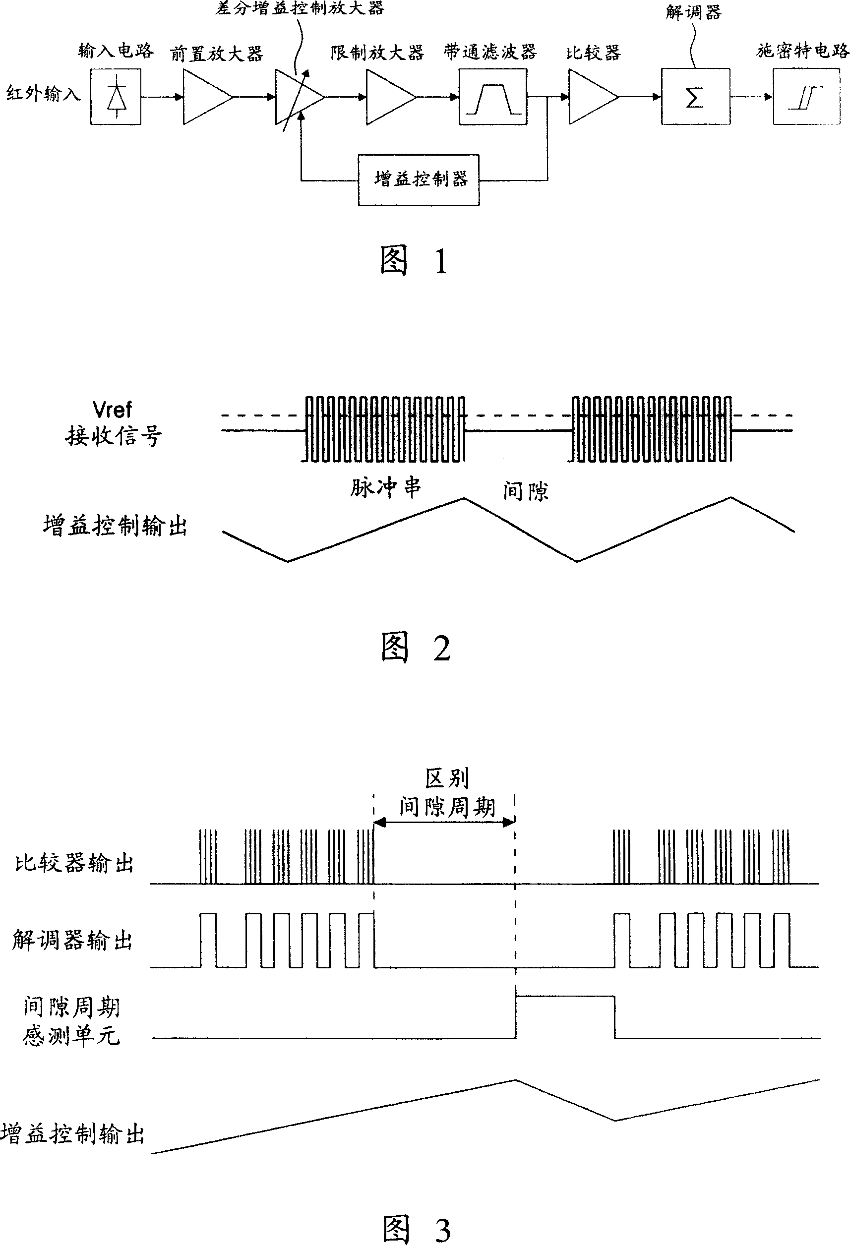
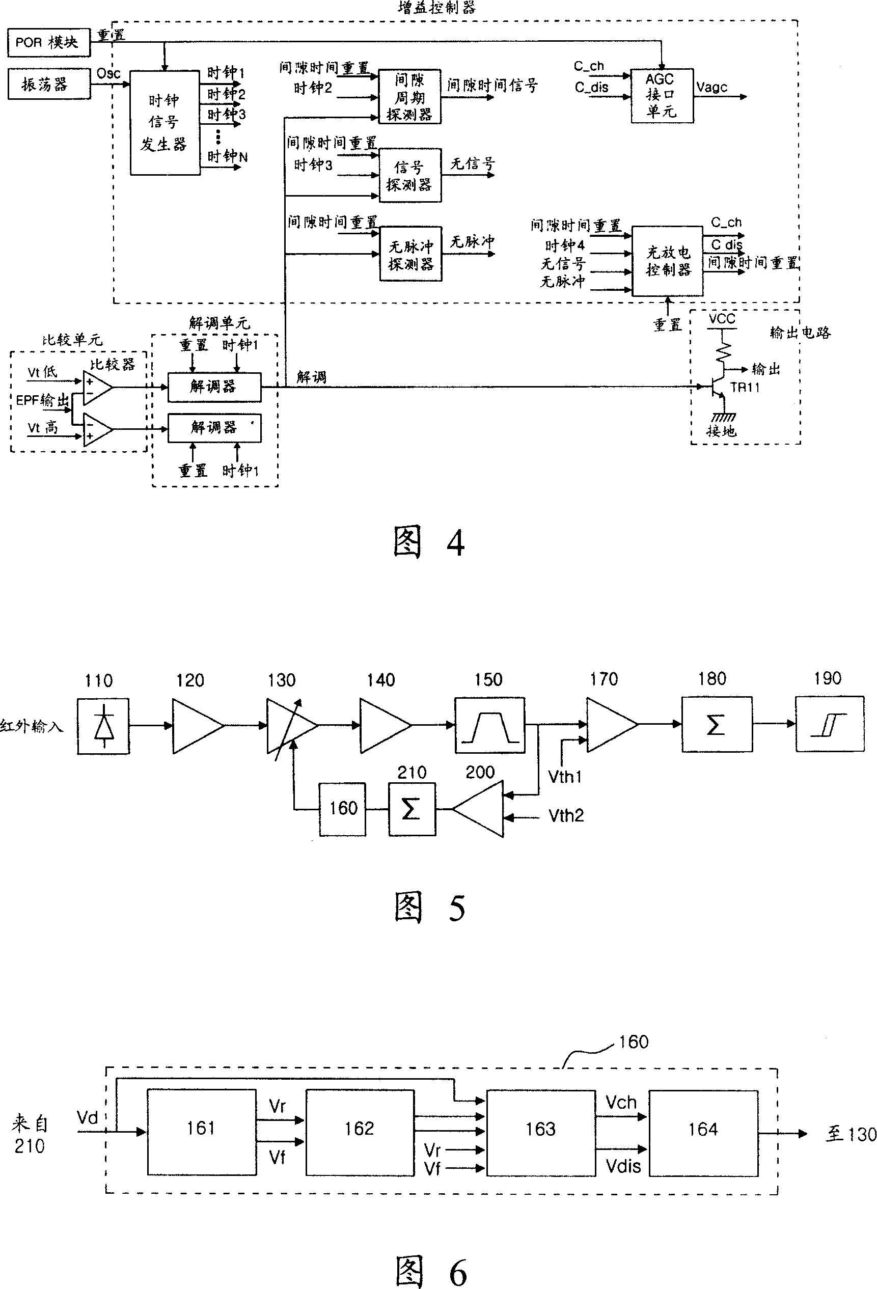
[0036] FIG. 5 is a block diagram showing an infrared receiver according to an embodiment of the present invention. The infrared receiver includes an input unit 110, a preamplifier 120, an automatic gain control amplifier 130, a limiting amplifier 140, a bandpass filter 150, a gain controller 160, first and second comparators 170 and 200, first and second demodulators 180 and 210, and an output unit 190.

[0037] The operation of the infrared receiver according to the embodiment of the present invention will be described below with reference to FIG. 5 .

[0038] The input unit 110 includes a photodiode, and converts an input optical signal into an electrical signal. The preamplifier 120 amplifies the converted electrical signal.

[0039] Automatic gain control amplifier 130 receives the output of preamplifier 120 and controls the gain ...


PUM


Abstract

Provided is an infrared-ray receiver for preventing the generation of the noise from the inner/external of the receiver. Pulse is generated in the input noise and signal. Distinguishing the noise andsignal by the pulse, thereby obtaining the quick attenuation of the noise and the adequacy time constant for the signal. When designing the integrate circuit, the infrared-ray receiver responds to theinput signal to charge and discharge in short time, therefore, the area of the integrate circuit can be reduced by insure adequacy time constant. Continuous noise source can be removed without usingoscillator in the chip, thereby keeping the infrared-ray receiver with high sensitivity. Furthermore, the quick charge relative to the continuous noise is reduced, thereby the time for generating error by the noise in the output can be reduced.

Description

technical field [0001] The present invention relates to an infrared receiver, and in particular to an infrared receiver including a gain controller capable of removing noise generated in the infrared receiver. Background technique [0002] An infrared receiver receives infrared signals from an infrared data transmitter such as an infrared remote control for a household appliance such as a television. [0003] FIG. 1 is a block diagram showing a conventionally used infrared receiver. The infrared receiver shown in FIG. 1 is disclosed in Korean Patent Registration Publication No. 322520 filed and registered by the applicant of the present invention. [0004] Referring to FIG. 1 , an input unit including a photodiode senses an infrared input signal received from the outside of the infrared receiver, and converts the sensed infrared input signal into an electrical signal. Since the converted electrical signal is relatively weak, the converted electrical signal is amplified thr...

Claims


Application Information

Patent Timeline
Patent Type & Authority Applications(China)
IPC IPC(8): H04B10/06G08C23/04H04B10/114H04B10/60
CPCH04B10/114H04B10/676H04B10/6931H04B10/697
Inventor 崔峻赫
Owner ALPHA HLDG
Why Eureka
Try Eureka