Device and methods for braking in a motor vehicle

A braking device and control device technology, applied in the direction of brakes, noise/vibration control, etc.

Inactive Publication Date: 2007-06-20
BAYERISCHE MOTOREN WERKE AG
View PDF1 Cites 3 Cited by
  • Summary
  • Abstract
  • Description
  • Claims
  • Application Information

AI Technical Summary

Problems solved by technology

The creaking noise can also be intentionally caused by the driver by selecting the appropriate brake release pressure

Method used


Image

  • Device and methods for braking in a motor vehicle

Examples


Embodiment Construction

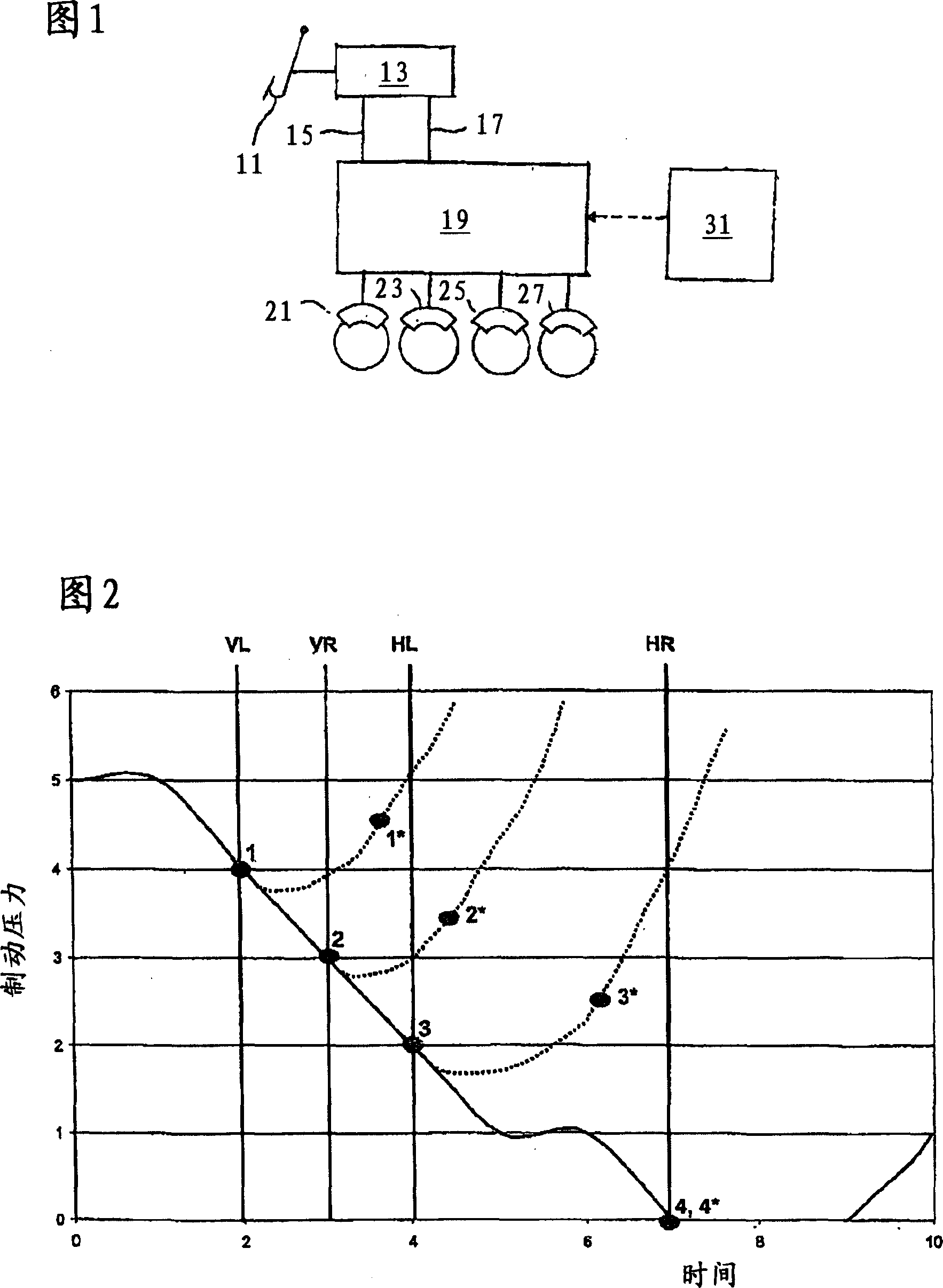
[0022] FIG. 1 shows a braking system for a vehicle (not shown) with friction brakes for each wheel. The brake device is designed in a known manner as a hydraulic or electrohydraulic friction brake and has a brake master cylinder 13 which can be mechanically actuated via a brake actuating device in the form of a brake pedal 11 , the brake master cylinder is hydraulically connected to a hydraulic assembly 19 via a first output line 15 of a first brake circuit and a second output line 17 of a second brake circuit. The four wheel brakes 21 , 23 , 25 , 27 of the vehicle are connected to the hydraulic unit 19 so that the brake pressures in the wheel brakes 21 , 23 , 25 , 27 can each be adjusted via the hydraulic unit 19 .

[0023] The detailed structure of the hydraulic unit 19 is known to the skilled person from the usual hydraulic or electrohydraulic brake systems in today's vehicles, which have driving stability control devices (eg ESP), anti-lock brake control devices ( ABS) or...


PUM


Abstract

The invention relates to a braking system and a method for braking a motor vehicle. According to the invention, a braking system for a motor vehicle comprises at least one brake operating device for wheel brakes (21, 23, 25, 27), embodied as friction brakes. The braking system is characterised in that a controller (31) is provided, which on a braked transition from moving to standstill from a given slow speed and from standstill moving up to a given slow speed, the wheel brakes are operated at differing times or at differing times with increasing braking force, or released at different times, or operated with reducing braking force.

Description

technical field [0001] The invention relates to a braking device and a method for braking a vehicle according to the preambles of claims 1 and 8 . Background technique [0002] For vehicles starting or stopping on hilly terrain, creaking noises (Knarzgerusch) may occur when the service brake is released or applied at low vehicle speeds due to slope forces, which are caused by vibrations in the wheel brakes, chassis and body cause. The stick-slip effect causes the wheel brakes to vibrate rigidly, which induces first-order bending of the shock strut. The body can even be excited via the chassis and assumes a so-called sound amplification function. The speed at which this creaking noise occurs is basically between 0 and 10km / h. [0003] In addition, the above-mentioned creaking noises occur in vehicles with automatic transmission, depending on the magnitude of the drive torque when stopping, for example at traffic lights, when the brake is released, at a sticking / slipping t...

Claims


Application Information

Patent Timeline
Patent Type & Authority Applications(China)
IPC IPC(8): B60T8/00
CPCB60T8/00F16D65/0006
Inventor G·艾希纳A·莱特纳
Owner BAYERISCHE MOTOREN WERKE AG
Why Eureka
Try Eureka