Valve for use in a fuel line of a motor vehicle

A technology for fuel delivery and motor vehicles, applied to fuel injection pumps, machines/engines, fuel injection devices, etc., to achieve the effects of simple structure, small valve body vibration characteristics, and simple production

Inactive Publication Date: 2007-06-20
CONTINENTAL AUTOMOTIVE GMBH
View PDF0 Cites 12 Cited by
  • Summary
  • Abstract
  • Description
  • Claims
  • Application Information

AI Technical Summary

Problems solved by technology

This is often a considerable disadvantage, especially in valves used as pressure-limiting valves in delivery lines leading to motor vehicle internal combustion engines, since the pressure in the delivery line should be constant independent of at volume flow
These known valves can therefore only be set for a defined volume flow range due to the rise of the characteristic curve

Method used


Image

  • Valve for use in a fuel line of a motor vehicle
  • Valve for use in a fuel line of a motor vehicle
  • Valve for use in a fuel line of a motor vehicle

Examples


Embodiment Construction

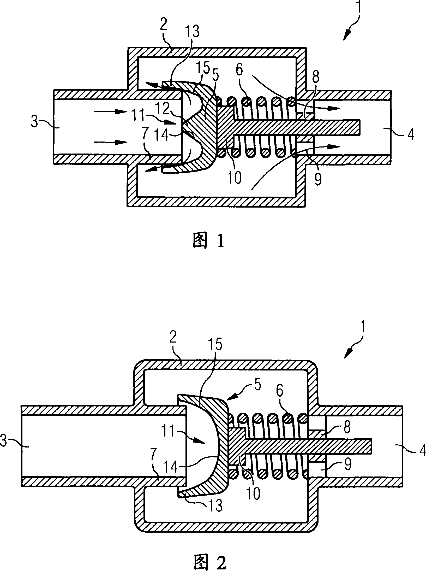
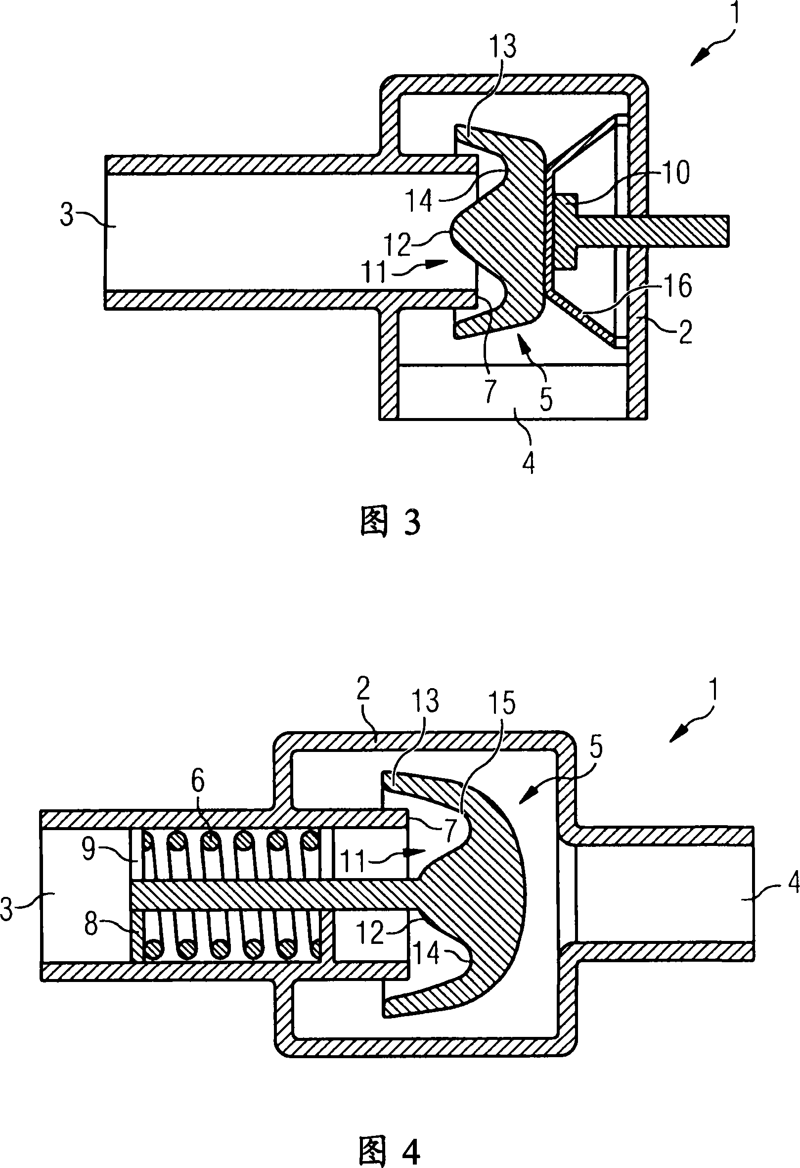
[0024] The valve shown in Figure 1 is installed in the fuel line as a check valve. The valve 1 has a housing 2 which has an inlet 3 and an outlet 4 on its two side faces, wherein the inlet 3 is inserted into the housing 2 . The inlet 3 and outlet 4 can be connected to pipe ends (not shown) of fuel pipes. The inlet 3 is closed by a valve body 5 which is pressed against the inlet 3 by a helical spring 6 against a sealing seat 7 . Furthermore, the valve body 5 has a receptacle 10 for the helical spring 6 on the side facing away from the sealing seat. The helical spring 6 is supported with its end facing away from the valve body 5 on a support body 8 which has perforations 9 for the passage of fuel.

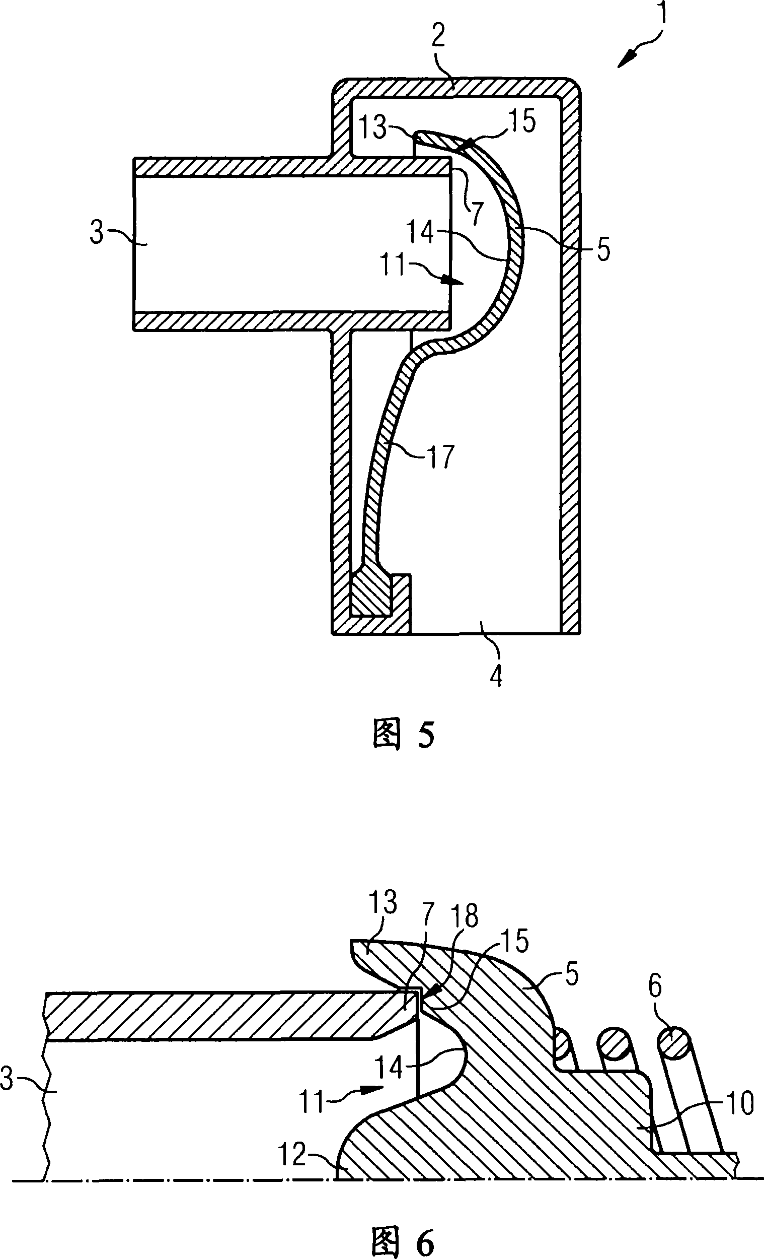
[0025] On the side facing the sealing seat 7 , the valve body 5 has a contour 11 formed by a centrally arranged central projection 12 and a radially outer peripheral projection 13 . The two projections 12 , 13 are connected to one another by means of the concavely formed surface 1...


PUM


Abstract

The invention concerns a valve (1) for use in a fuel line of a motor vehicle, comprising a sealing seat (7), a valve body (5) which closes the sealing seat (7) and a spring device (6, 16, 17), which pre-tensions the valve body (5) against the sealing seat (7). The side of the valve body (5) facing the sealing seat (7) has a contour (11) for deflecting the volume flow over an angle of greater than 90 DEG and the outer diameter of the contour (11) is greater than the diameter of the sealing seat (7).

Description

technical field [0001] The invention relates to a valve for use in a fuel delivery line of a motor vehicle, having a sealing seat, a valve body closing the sealing seat, and a spring device biasing the valve body towards the sealing seat. These valves are used in fuel lines as check valves or overflow valves. Background technique [0002] Valves of this type are already known in the prior art. The valve is often arranged in a housing which has an inlet and an outlet. The inlet has a sealing seat on which a valve body biased by spring means is arranged and by which the valve body closes off the inlet. Accordingly, further flow of fuel flowing through the inlet is prevented. Only when the pressure in the inlet exceeds the force generated by the spring, the valve body is removed from the sealing seat. Fuel can flow around the valve body through the now open inlet to the outlet. [0003] Various disc-shaped parts are used as the valve body. In order to improve the flow aro...

Claims


Application Information

Patent Timeline
Patent Type & Authority Applications(China)
IPC IPC(8): F02M55/02F16K15/02F16K15/06
CPCF02M59/462F16K15/026F16K15/00F02M63/0054Y10T137/7837Y10T137/7922F02M55/02F16K15/02F16K15/06
Inventor 洛塔尔·迪肯沙伊德迪尔克·默林
Owner CONTINENTAL AUTOMOTIVE GMBH
Why Eureka
Try Eureka