Method and apparatus for driving a power MOS device as a synchronous rectifier

A synchronous rectifier, MOS device technology, applied in output power conversion devices, AC power input conversion to DC power output, electrical components and other directions, can solve the problems of low offset comparators, difficult to achieve practical application of circuits, etc.

Inactive Publication Date: 2007-06-20
INTERNATIONAL RECTIFIER COEP
View PDF0 Cites 5 Cited by
  • Summary
  • Abstract
  • Description
  • Claims
  • Application Information

AI Technical Summary

Problems solved by technology

[0010] Practical applications of such circuits are difficult because the thresholds must

Method used


Image

  • Method and apparatus for driving a power MOS device as a synchronous rectifier
  • Method and apparatus for driving a power MOS device as a synchronous rectifier
  • Method and apparatus for driving a power MOS device as a synchronous rectifier

Examples


Embodiment Construction

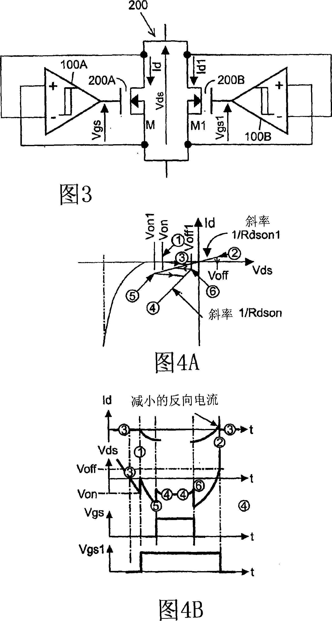
[0023] The invention will now be described in more detail with reference to the accompanying drawings. Figure 3 shows a circuit embodying the invention. The operation of the circuit shown in Fig. 3 is as follows: The power MOSFET transistor 200 according to Fig. 3 comprises a first large device 200A and a second small device 200B. The first Schmidt flip-flop 100A drives the gate of device 200A, and the second Schmidt flip-flop 100B drives the gate of device 200B. If an AC waveform is applied to the drain-source path of the device for rectification, the operating point will eventually reach point 1 shown in Figure 4A, where the condition Vds=-Von1 is satisfied. As a result, the output of the Schmidt flip-flop will go high and MOSFET 200B will turn on. If the current increases enough to reach point 5 of Figure 4A, main power MOSFET 200A will also turn on. When the current decreases such that point 6 of FIG. 4A is reached, main power MOSFET 200A returns to the off state. Even...


PUM


Abstract

A synchronous rectifier comprising a MOSFET device, and a gate driver for driving the gate of the MOSFET device, the MOSFET device comprising first and second MOSFET transistors coupled with their drain-source paths in parallel to receive an alternating current waveform for rectification by the drain- source paths of the MOSFET transistors, the first transistor having a low Rdson and the second transistor having a high Rdson whereby the apparent Rdson of the MOSFET device is increased when the current through the MOSFET device is below a threshold thereby enabling zero crossing detection.

Description

[0001] Cross References to Related Applications [0002] This application claims benefit and priority of U.S. Provisional Application S.N. 60 / 418,417, filed October 11, 2002, entitled "Improved Method to Drive a Power MOS Device As a Synchronous Rectifier," which is hereby incorporated by reference in its entirety The disclosed content is incorporated into this application. technical field [0003] The present invention relates to a method and a device for driving a power semiconductor device, in particular to a method and a device for driving a power MOS device as a synchronous rectifier. Background technique [0004] Driven by the increasing need for increased efficiency, and made feasible by the availability of ultra-low Rdson (on-resistance) power MOSFETs, it has become popular to replace PN or Schottky rectifier diodes with MOSFETs in low-voltage applications . A typical example is a car's alternator. By replacing the diode bridge rectifier (which drops more than two...

Claims


Application Information

Patent Timeline
IPC IPC(8): H02M7/00
CPCY02B70/1475
Inventor B·C·那达X·德富如特斯A·墨瑞尔
Owner INTERNATIONAL RECTIFIER COEP
Why Eureka
Try Eureka