Electrohydraulic hammer

An electro-hydraulic hammer and hydraulic technology, applied in the field of hydraulic electro-hydraulic hammer, can solve the problems of complexity, uncontrollable return speed, easy to hit the top, etc., and achieve obvious buffer function, good process requirements, and the effect of meeting process requirements.

Inactive Publication Date: 2007-06-27
ANYANG FORGING PRESS MACHINERY IND
View PDF2 Cites 22 Cited by
  • Summary
  • Abstract
  • Description
  • Claims
  • Application Information

AI Technical Summary

Problems solved by technology

All actions of the forging hammer require two sets of control systems, which are relatively complicated and cannot achieve stepless speed regulation
The patent application number is 02218450.3. The system is relatively simple, but it cannot realize slow down and slow up motions, nor can it stop the hammer at any position. The hammer rod can only be stabilized at the upper de

Method used


Image

  • Electrohydraulic hammer
  • Electrohydraulic hammer
  • Electrohydraulic hammer

Examples


Embodiment Construction

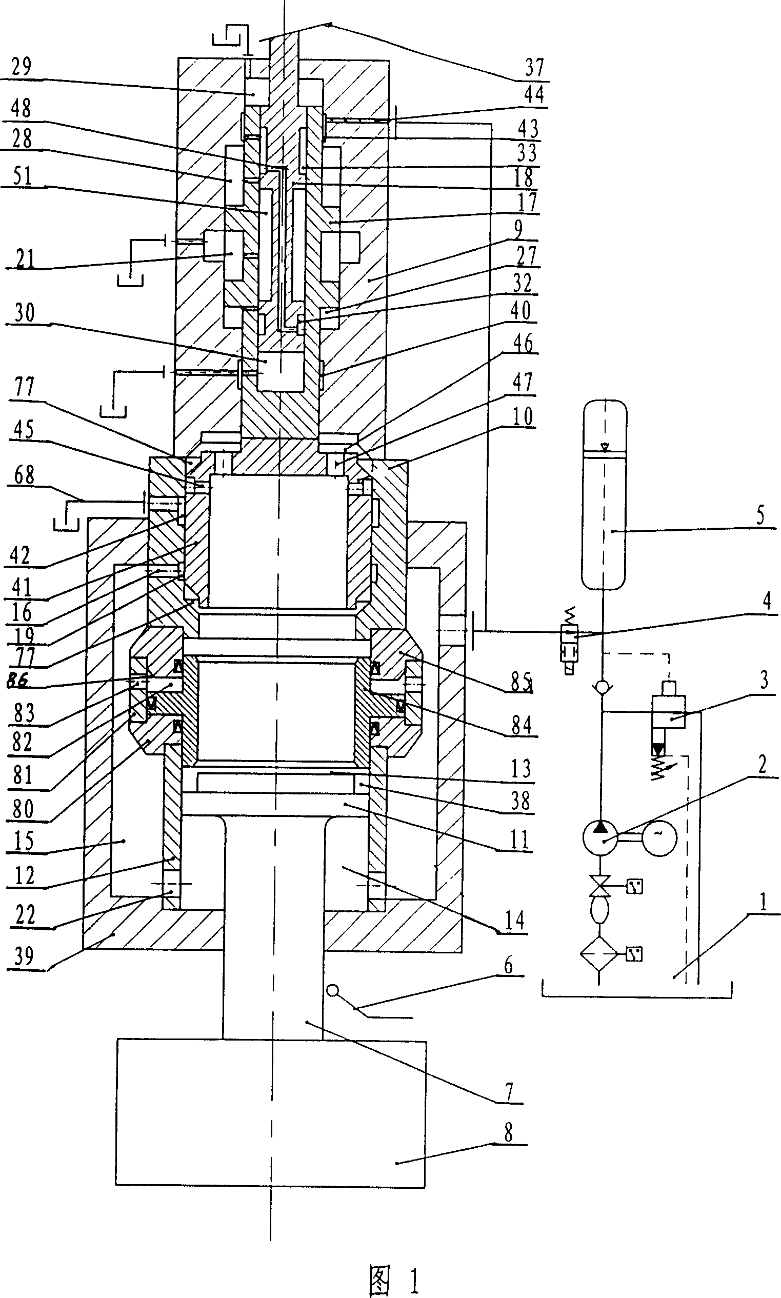
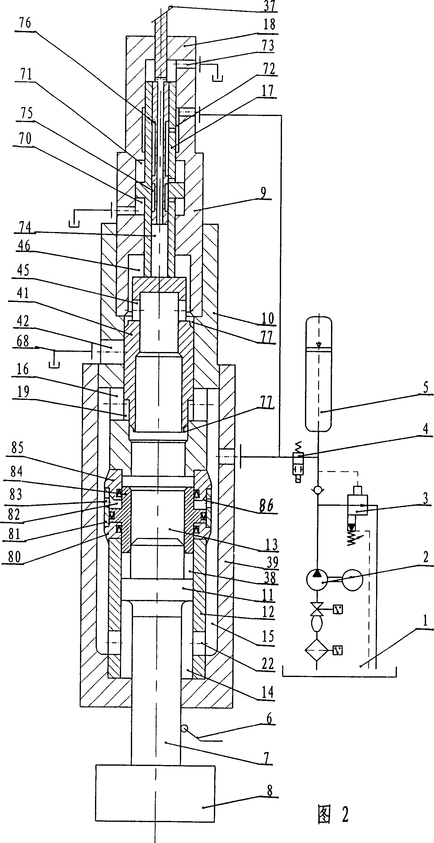
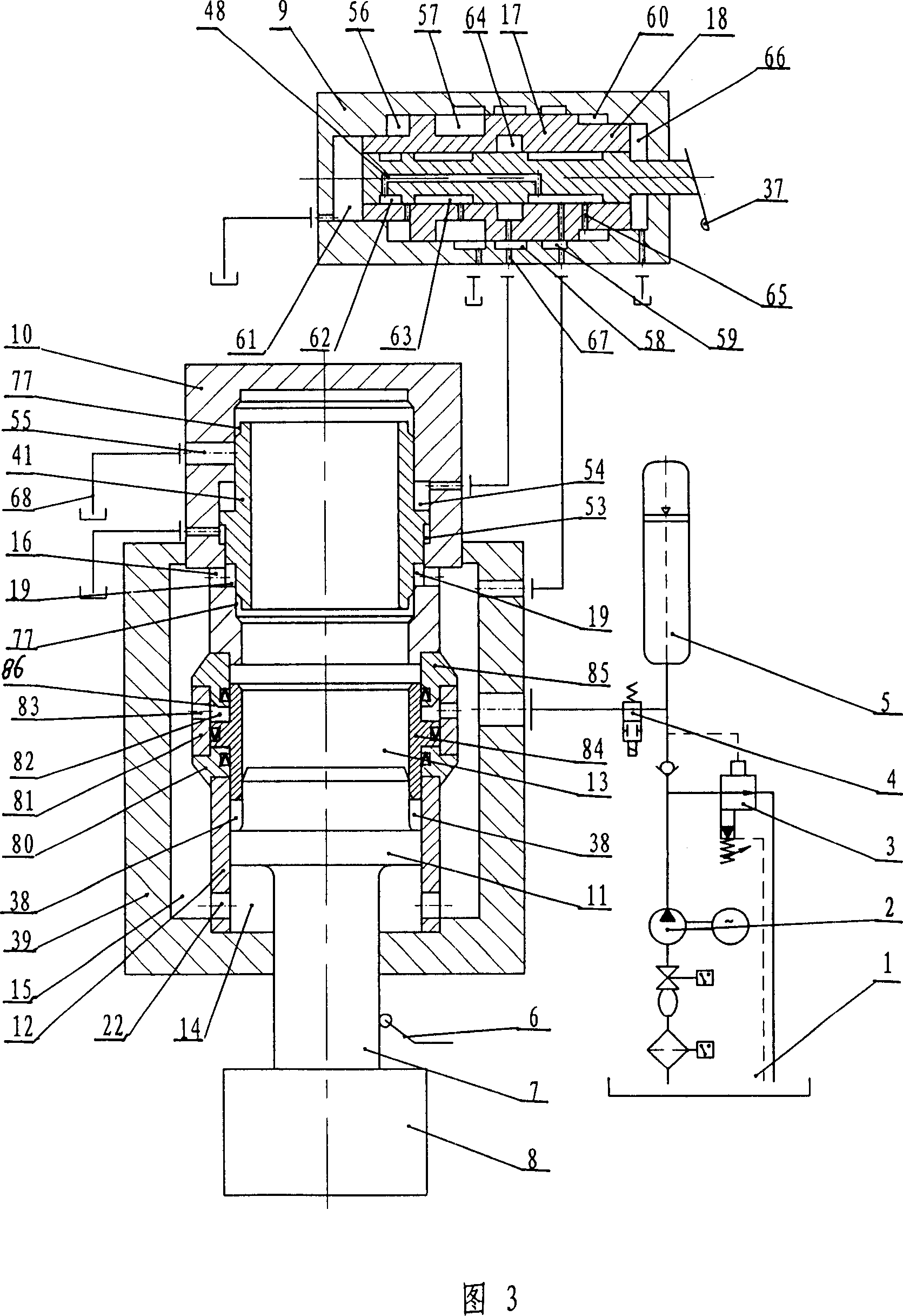
[0019] As shown in Figure 1, the anti-bump hydraulic electro-hydraulic hammer of the present invention includes a machine base 39 and a hammer rod driving oil cylinder installed in the machine base 39 along the vertical direction, and a control valve is installed above the hammer rod driving oil cylinder body 12, as shown in Fig. The control valve shown in 3 is the state when the spool 18 is at zero position, the upper end of the hammer rod 7 with the hammer head 8 at the lower end is connected with the piston 11 in the cylinder body 12 of the hammer rod driving oil cylinder, and the upper and lower two sides of the piston 11 The end has an upper cylinder chamber 13 and a lower cylinder chamber 14, the effective working area of ​​the piston 11 in the upper cylinder chamber 13 is greater than its effective working area in the lower cylinder chamber 14, and the lower cylinder chamber 14 communicates with the high-pressure oil through at least one lower through hole 22. The channe...


PUM


Abstract

The electrohydraulic hammer includes a frame, a hammer stem driving cylinder, a hydraulic source, a hammer stem with hammer head in the lower end and upper end connected to the piston inside the hammer stem driving cylinder, an upper cylinder chamber and a lower cylinder chamber in the ends of the piston, and an operating valve with valve body, a servo valve inside the valve body and valve core capable of sliding inside the servo valve. When the valve core is in different position inside the servo valve, the operating valve can close the oil inlet passage of the upper cylinder chamber, the oil exhaust passage, or both the oil inlet passage and the oil exhaust passage. Between the driving cylinder and the operating valve, there is one buffering cylinder with excellent buffering effect to avoid bumping top after the hammer head reaches the top dead point.

Description

technical field [0001] The invention relates to an electro-hydraulic hammer, in particular to a hydraulic electro-hydraulic hammer used for forging and piling machinery and other hydraulically driven mass blocks to perform work. Background technique [0002] The existing fully hydraulically driven electro-hydraulic hammer has a structure that the lower chamber of the hammer rod piston is normally connected with high-pressure oil, and the oil in the upper chamber of the hammer rod piston is controlled by the control valve to achieve the strike and return of the forging hammer. For example, the patent number is The patents of 93120993.5 and 02218450.3 are two technical solutions disclosed in the book. The principles of these two technical solutions are basically the same, but the structure and principle of the control valve are different. The application number is 93120993.5. The patent uses hydraulic pressure to directly drive the piston, and the piston rod drives the cone va...

Claims


Application Information

Patent Timeline
IPC IPC(8): B21J7/28B21J7/46E02D7/06E02D7/14B25D9/02B25D9/12B25D9/16B25D9/26
Inventor 夏德仕
Owner ANYANG FORGING PRESS MACHINERY IND
Why Eureka
Try Eureka