Vertical shaft wind power generator

A wind power generation device, vertical axis technology, applied in wind power generator components, electromechanical devices, wind power generation, etc., can solve the problems of lack of competitiveness for power generation, poor adaptability to wind speed changes, and constant power generation, etc., to achieve wind energy utilization High efficiency, strong adaptability, cost-effective effect

Inactive Publication Date: 2007-06-27
廖振雷
View PDF0 Cites 15 Cited by
  • Summary
  • Abstract
  • Description
  • Claims
  • Application Information

AI Technical Summary

Problems solved by technology

[0004] Vertical axis wind turbines are divided into two main categories, one is to use aerodynamic resistance to do work, the typical structure is an S-shaped wind wheel, which is composed of two semi-cylindrical blades whose axes are staggered, and its advantage is the starting torque Larger, the disadvantage is that due to the asymmetrical airflow around the wind rotor, it generates lateral thrust; for larger wind turbines, it is difficult to adopt this structural form due to the limitation of deflection and safety limit stress ; The wind energy utilization coefficient of general S-type wind turbines is lower than that of high-speed vertical-axis or horizontal-axis wind turbines, and the power output provided by the wind rotor with a certain size, weight and cost is low, so it is not competitive for power generation
The other type is to use the lift of the airfoil to do work. The most typical is the Darrieux type wind turbine, which has a high work efficiency in the case of high-speed wind, but the work efficiency is poor in the case of low-speed wind. Due to the wind direction and wind speed The range of change is very large. In wind power generation, the wind rotor has high requirements for wind direction and wind speed adaptability. The wind turbine

Method used


Image

  • Vertical shaft wind power generator
  • Vertical shaft wind power generator
  • Vertical shaft wind power generator

Examples


Embodiment approach

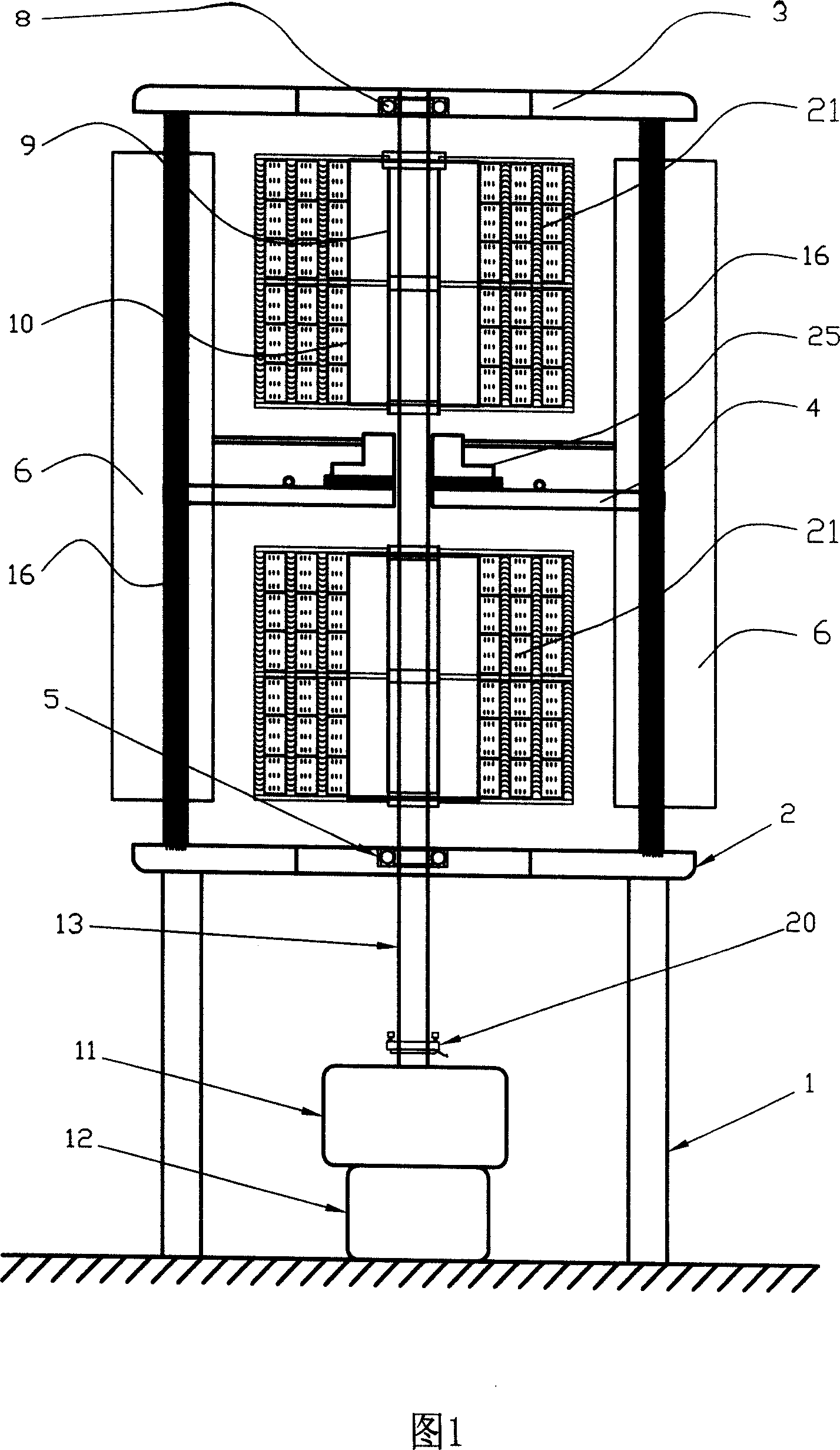
[0038] As shown in Figure 1, a vertical axis wind power generation device has: a vertically arranged rotating shaft 13, a wind wheel mechanism 21 installed on the rotating shaft 13, a support frame 1 for supporting the rotating shaft 13 and the wind wheel mechanism 21, The speed-increasing gear box 11 connected to the bottom of the rotating shaft 13 is connected to the generator 12 of the speed-increasing gear box 11, and it also includes an upper fixed plate 3, a middle fixed plate 4, a lower fixed plate 2, and 8 support columns 16, 8 Block wind deflector 6 and wind deflector guide 25, wherein,

[0039] The support frame 1 is fixedly installed on the ground or a building, the lower fixed plate 2 is fixedly connected to the support frame 1, the speed-increasing gear box 11 and the generator 12 are arranged under the support frame 1, and are fixedly installed on the support frame 1. on the ground or on buildings;

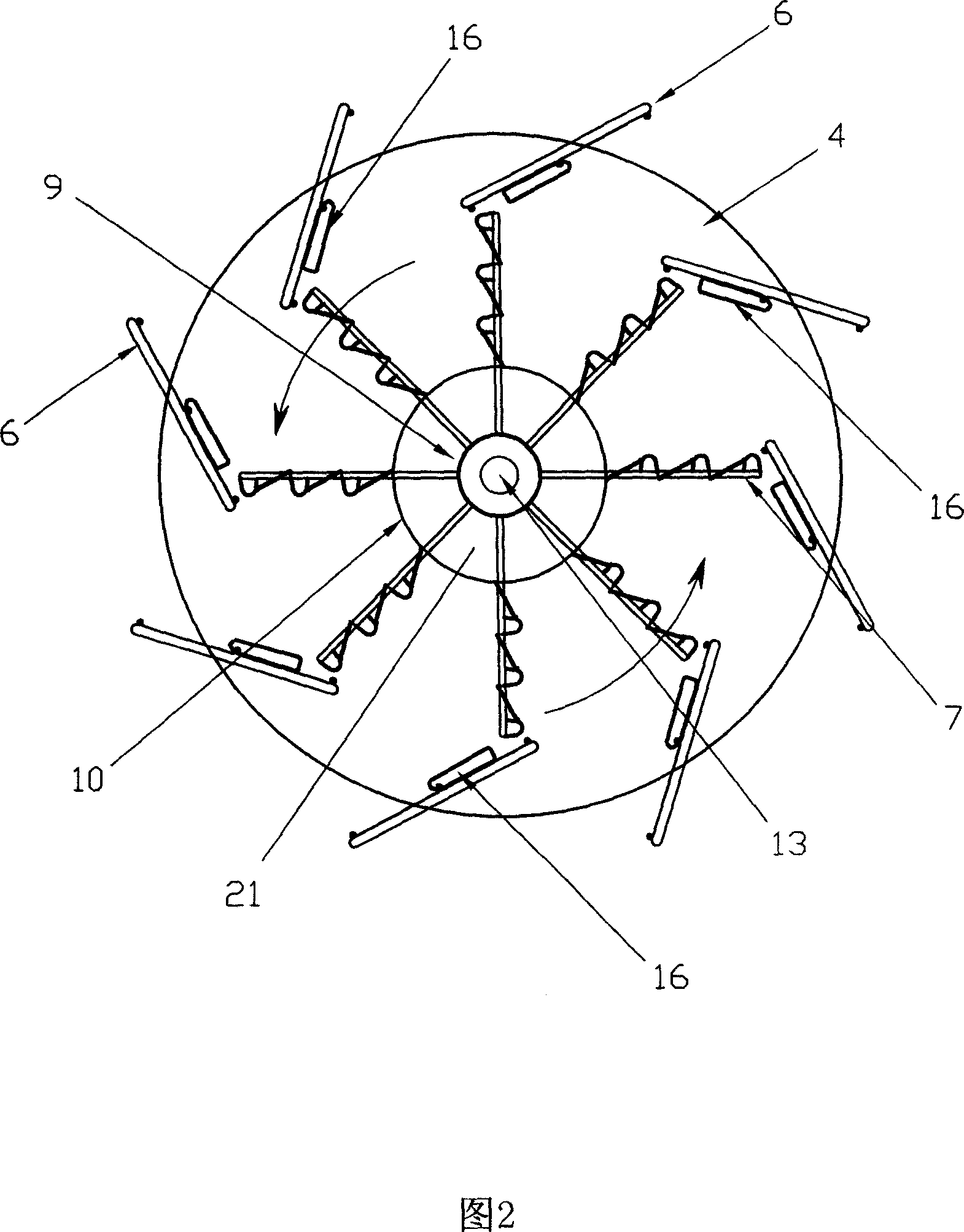
[0040] As shown in Figure 2, eight support columns 16 are arra...


PUM


Abstract

A wind-driven electric generator with a vertical rotary shaft is composed of a vertical rotary shaft, a wind driven wheel unit consisting of upper and lower wheels, upper and lower fixing discs and upper and lower bearings, a supporting frame consisting of 2N vertical columns, where N=2-6, and 2N wind guiding plates linked to said vertical columns (one to one) and their guiders.

Description

【Technical field】 [0001] The present invention relates to a wind power generation device, in particular to a vertical axis wind power generation device capable of efficiently utilizing wind energy to generate electricity. When there is a high wind speed, the guide of the wind deflector is automatically adjusted to control the air intake of the wind wheel mechanism, so that the wind wheel mechanism can run at the rated speed. 【Background technique】 [0002] At present, there are mainly two types of devices used for wind power generation: one is the horizontal axis high-speed wind generator, and the other is the vertical axis wind generator; the vertical axis wind generator can be divided into two types according to the form of work: using aerodynamic The vertical axis wind turbine that does work (such as S-type wind turbine) and the vertical axis wind turbine that uses the lift of the airfoil to do work (such as Darrieux type wind turbine). Among them, the horizontal axis hig...

Claims


Application Information

Patent Timeline
IPC IPC(8): F03D9/00F03D3/00F03D3/04F03D3/06F03D7/06F03D11/04H02K7/18F03D9/25F03D13/20
CPCY02E10/728Y02E10/74
Inventor 廖振雷
Owner 廖振雷
Why Eureka
Try Eureka