Drawbench for carbon steel metal material

A technology of metal materials and wire drawing machines, which is applied in the direction of metal wire drawing, wire drawing dies, metal processing equipment, etc., and can solve the problems of troublesome loading and unloading, long heating, heat preservation and cooling time, waste products and broken wires, etc.

Inactive Publication Date: 2007-07-11
FUNDANT CHANGZHOU ADVANCED METAL TECH
View PDF0 Cites 5 Cited by
  • Summary
  • Abstract
  • Description
  • Claims
  • Application Information

AI Technical Summary

Problems solved by technology

The above annealing method takes a long time for heating, heat preservation and cooling, requires a lot of heat energy, and it is troublesome to install and take out the furnace.
In addition, during the drawing process, the drawing die is easy to wear and form grooves, which is prone to waste and broken wires, which seriously affects the drawing quality and drawing cost

Method used


Image

  • Drawbench for carbon steel metal material

Examples


Embodiment Construction

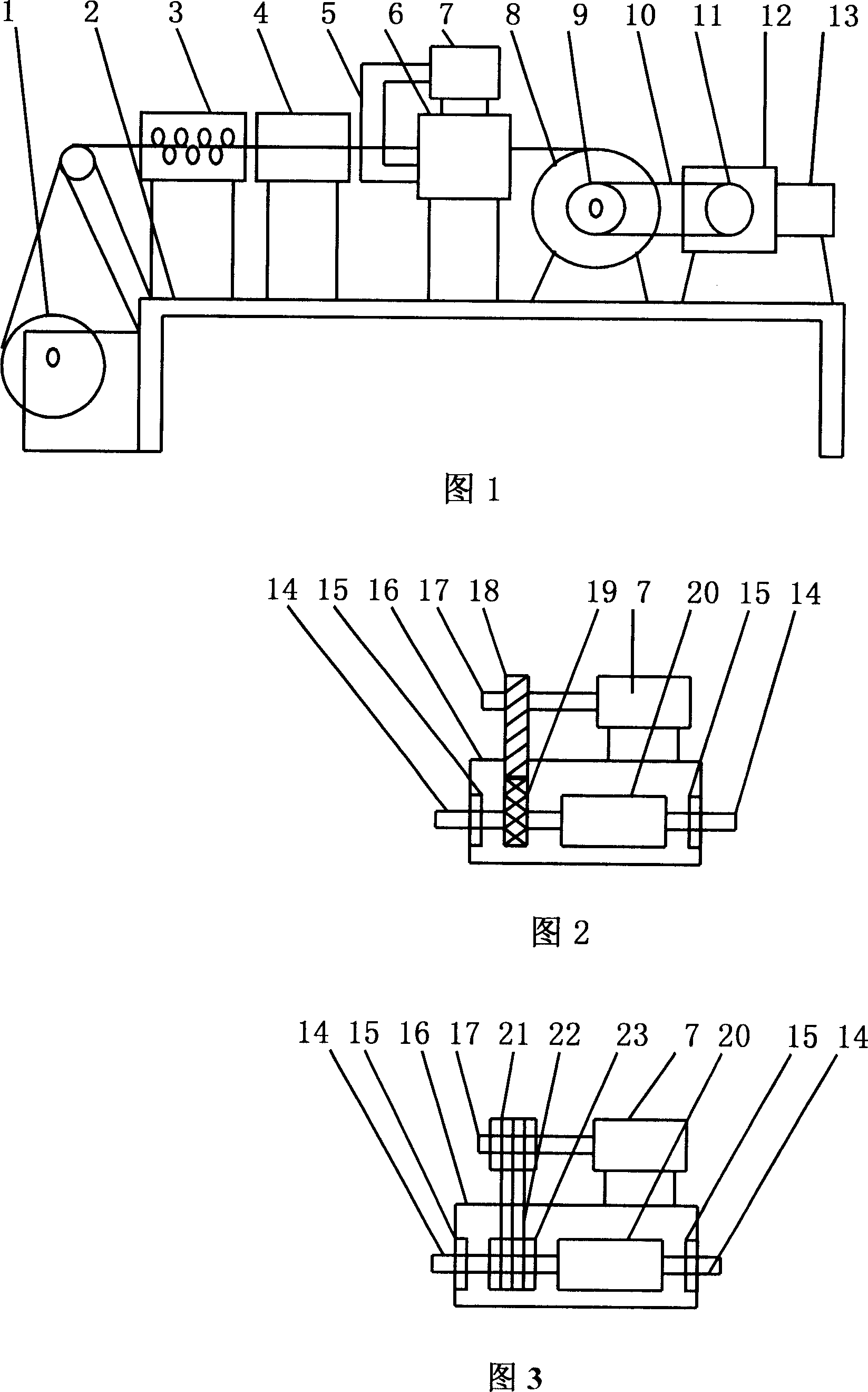
[0017] A wire drawing machine for carbon steel metal materials, as shown in Figure 1: a pay-off frame 1, a straightening machine 3, a wire drawing die device 6, a wire receiving frame 8, a speed regulating device 12 and a large motor 13 are fixed sequentially from left to right On rack 2. The large motor 13 is connected with the speed regulating device 12, and the speed regulating device 12 is connected with the wire receiving frame 8 through the belt pulley B11, the belt A10 and the belt pulley A9. An induction heater 4 is also installed on the frame 2 between the straightening machine 3 and the drawing die device 6 . Bearings 15 are housed at the left and right ends of the wire drawing die box 16 of the wire drawing die device 6 . The wire drawing die box 20 left and right ends that are contained in the wire drawing die box 16 are equipped with shaft rollers 14, and the two ends shaft rollers 14 are all mounted on the wire drawing die box 16 by bearings 15 at both ends. Th...


PUM


Abstract

The invention relates to a carbon steel wire drawer, wherein it comprises expand support, align machine, sensitive heater, drawer mould, collecting support, speed adjuster and large motor fixed from left to right on the frame; the large motor via speed adjuster, belt disc B, belt A, and belt disc A is connected to the collecting support; the mould box via roller, bearing is connected to the mould box; the small motor on the box via connector is connected to the mould box. The invention can make the force uniform on the mould hole and avoid groove on the mould hole, to improve product quality and reduce cost.

Description

Technical field [0001] The invention relates to a wire drawing machine, in particular to a carbon steel metal material wire drawing machine. Background technique [0002] At present, metal wire drawing machines, especially high and medium carbon steel metal material wire drawing machines, cannot directly cold draw high and medium carbon steel metal materials. Generally, it needs to be heated to about 800 degrees in the furnace and kept for about 4 hours, and then naturally cooled to room temperature. Carbon steel metal materials can only be cold drawn after the above annealing treatment. The commonly used annealing methods are bell furnace annealing or pit furnace annealing. In the above-mentioned annealing method, the heating, heat preservation and cooling time are long, and a lot of heat energy is required, and it is troublesome to install and take out the furnace. In addition, during the drawing process, the wire drawing die is easy to wear and grooves are formed, which...

Claims


Application Information

Patent Timeline
Patent Type & Authority Applications(China)
IPC IPC(8): B21C1/12B21C9/00B21C3/12B21C19/00
Inventor 蒋阿生
Owner FUNDANT CHANGZHOU ADVANCED METAL TECH
Why Eureka
Try Eureka