Blade or vane for a rotary machine

A rotary and mechanical technology, applied in the direction of mechanical equipment, blade support components, engine components, etc., can solve the problems of being blocked in the matrix, blocking the matrix passage, reducing the cooling performance of the system, etc., to reduce the temperature difference and reduce the flow rate. The effect of increasing the flow area and improving the cooling efficiency

Inactive Publication Date: 2007-07-11
SIEMENS AG
View PDF3 Cites 11 Cited by
  • Summary
  • Abstract
  • Description
  • Claims
  • Application Information

AI Technical Summary

Problems solved by technology

[0004] Although this prior art cooling system is capable of effectively cooling the component, if the cooling fluid is not sufficiently pure, it may happen that foreign particles in the cooling fluid may become lodged in the matrix
Worse, some of the matrix vias may become clogged close to the leading edge, reducing the cooling performance of the system

Method used


Image

  • Blade or vane for a rotary machine
  • Blade or vane for a rotary machine
  • Blade or vane for a rotary machine

Examples


Embodiment Construction

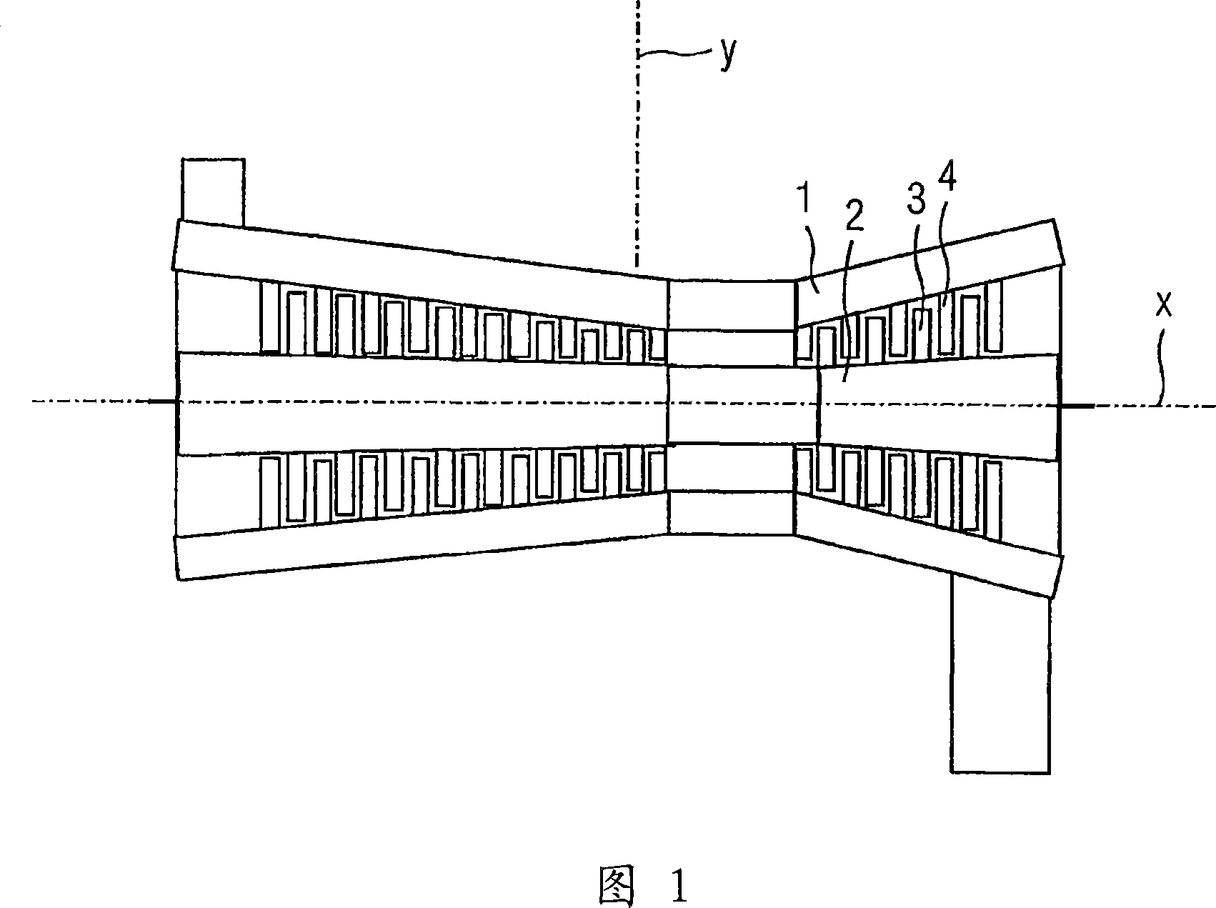
[0027] FIG. 1 schematically discloses a gas turbine with a stationary housing 1 and a rotor 2 rotatable within the housing 1 about an axis of rotation x. The gas turbine includes a plurality of rotor blades 3 mounted to a rotor 2 and a plurality of stationary vanes 4 mounted to a casing 1 .

[0028] Each rotor blade 3 and guide vane 4 thus forms a component of a gas turbine. Although the following description refers to the assembly in the form of a rotor blade 3 , it will be appreciated that the invention may also be applied to a vane 4 and that the features described hereinafter may also be included in a stationary vane 4 .

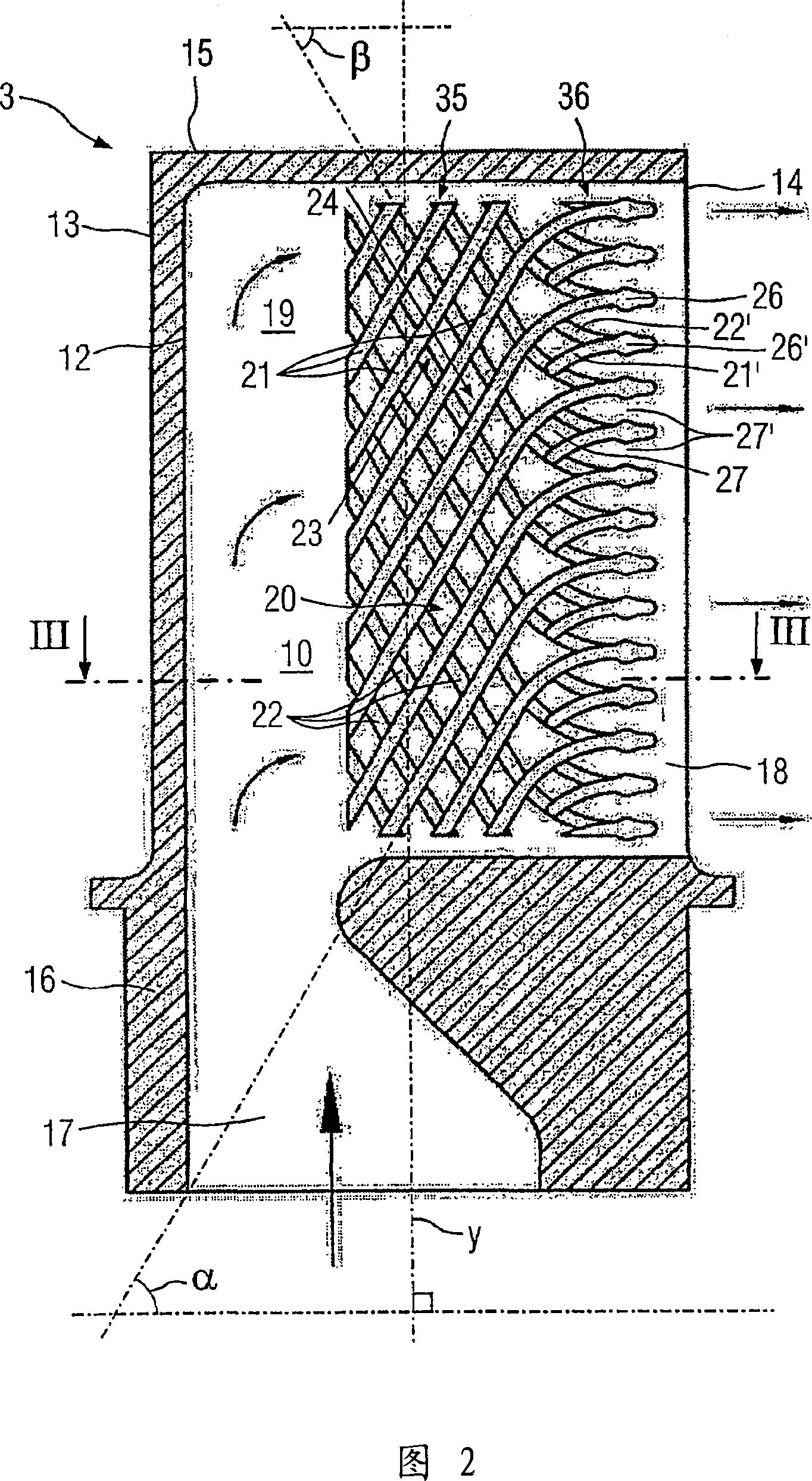
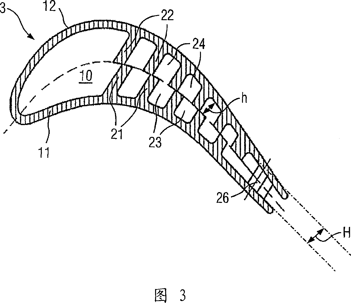
[0029] The above-mentioned assembly, namely in this case the rotor blade 3 , is further disclosed in FIGS. 2 and 3 . The rotor blade 3 comprises an inner space 10 delimited by a first wall 11 and an opposite second wall 12 . The first wall 11 and the second wall 12 face each other. The first wall 11 is arranged on the pressure side of the rotor blade ...


PUM


Abstract

A component defines a blade or a vane for a rotor rotatable about a rotary axis (x). An inner space (10) of the component is limited by first and second walls (12), and forms a passage for a cooling fluid. First and second ribs (21, 22) project form the first and second walls, respectively, and extend in parallel to each other to form channels for the fluid from a leading end to a trailing end of the ribs. The ribs extend along a first and a third direction, respectively, in the proximity of the leading end and along a second direction and fourth direction, respectively, in the proximity of the trailing end. The first direction is inclined in relation to the second direction. The third direction is inclined in relation to the fourth direction. The first direction intersects with the third direction. The ribs extend from the leading end to the trailing end along a continuously curved path.

Description

technical field [0001] The present invention generally relates to an assembly of a turbomachine, particularly a gas turbine having a rotor rotatable about an axis of rotation. The assembly includes guide vanes or rotor blades for gas turbines. [0002] In particular, the invention relates to an assembly defining one of a blade and a vane for a rotary machine having a rotor rotatable about an axis of rotation, the assembly comprising first The wall and the second wall define and have an inner space with an inlet and an outlet, wherein the inner space forms a coolant channel from the inlet to the outlet; first ribs protrude from the first wall and extend substantially parallel to each other to form The first fluid passage from the front end of the first rib (21) to the rear end of the first rib, wherein the first rib (21) extends from the front end to the rear end along the first direction near the front end and along the second direction near the rear end The above-mentioned ...

Claims


Application Information

Patent Timeline
Patent Type & Authority Applications(China)
IPC IPC(8): F01D5/18
CPCF01D5/187F05D2260/22141F05B2260/2241
Inventor 马茨·安纳菲尔特安德雷·舒金瑟奇·舒金
Owner SIEMENS AG
Why Eureka
Try Eureka