
Transistor test fixture with integrated couplers and method

a technology of couplers and test fixtures, applied in the direction of individual semiconductor device testing, instruments, material analysis, etc., can solve the problems of reducing the higher harmonic components, affecting the reconstitution of original signal forms, and affecting the distortion of higher tones

Active Publication Date: 2018-06-19
TSIRONIS CHRISTOS
View PDF5 Cites 7 Cited by
  • Summary
  • Abstract
  • Description
  • Claims
  • Application Information

AI Technical Summary

Benefits of technology

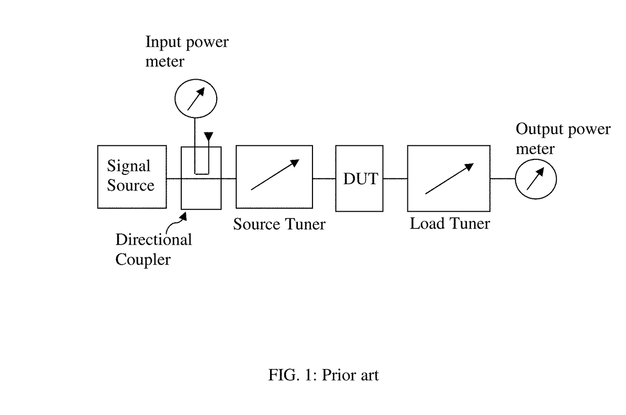
The patent text describes a method for testing RF transistors in microwave frequencies using a load pull or source pull test method. The test involves using impedance tuners to systematically characterize the transistor under various load and source impedance conditions. The text also discusses the use of Fourier analysis to describe the non-linear behavior of transistors at high power. The technical effect of the patent is to provide a more accurate and reliable method for testing RF transistors in microwave frequencies.

Problems solved by technology

However parasitic components, loss and low pass behavior of the network reduce the higher harmonic components significantly (FIG. 14); then reconstitution of the original signal form is affected negatively.
This is the typical problem in analog telephony and associated distortion of the higher tones in voice or music transmission using long cables between the amplifier and the speakers.
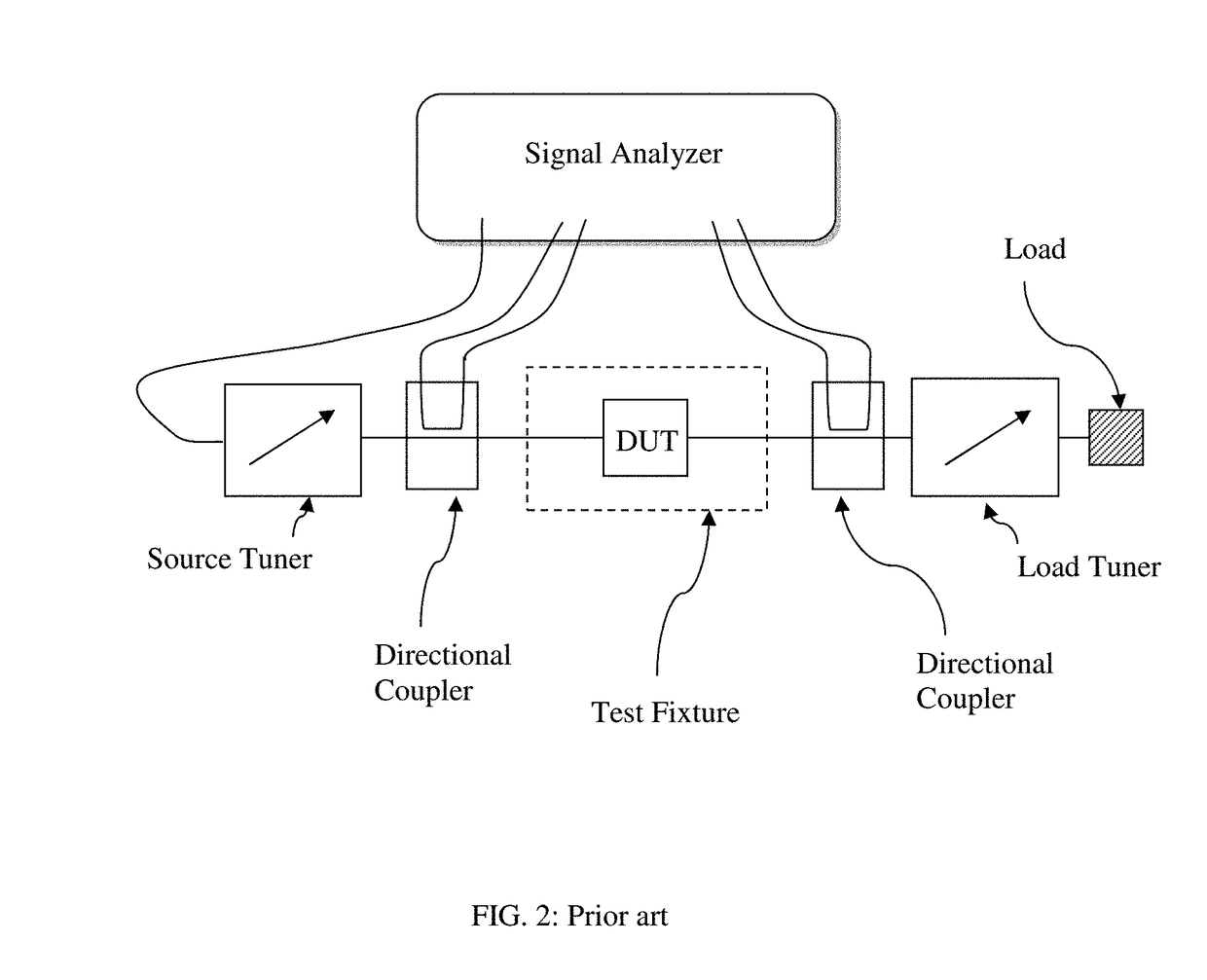
However such a setup has insertion loss and signal deformation due to parasitic components of the connectors between couplers and test fixture and transmission lines inside the fixtures and is therefore not an optimum embodiment.

Method used


Image

  • Transistor test fixture with integrated couplers and method
  • Transistor test fixture with integrated couplers and method
  • Transistor test fixture with integrated couplers and method

Examples


Embodiment Construction

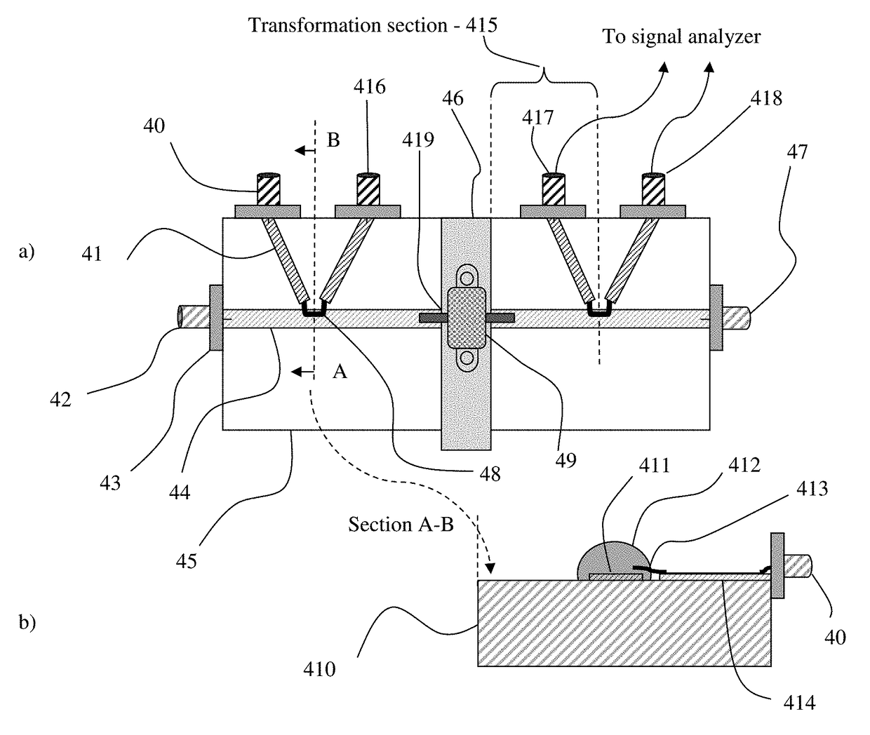
[0034]Regular transistor test fixtures come in two basic forms: Micro-strip fixtures (FIG. 3) or coaxial fixtures (FIG. 6). Micro-strip fixtures come in form of simple micro-strip (FIG. 3), where there is a continuous ground plane below the micro-strip. All types of test fixtures are being enhanced by adding signal coupling devices as close to the DUT as possible; the directional signal couplers (48, 56, 72, 83, 84, 117, 139) are created either through capacitive (electrical) or inductive (magnetic) field coupling (48, 72) of a set of electrical (84) or magnetic (83) sensors.

[0035]A typical micro-strip transistor test fixture (TTF, FIG. 3) comprises two coaxial signal ports, an input port (30) and an output port (37). A dielectric substrate (38) is soldered or mechanically mounted tightly on a metallic block (315) which serves as electrical ground and heat sink for the thermal energy dissipated by the transistor (33). The signal travels on the micro-strip conductor (31) to the input...


PUM


Abstract

Microwave transistor test fixtures, both micro-strip and coaxial, include integrated wideband directional signal sensors / couplers and allow the detection of the main signal and its harmonic components, injected into and delivered by a transistor in high power operation mode, by using a phase-calibrated network or signal analyzer and allows this way the reproduction of real time signal waveforms. The fixtures are best calibrated using equivalent TRL calibrated fixtures allowing overcoming the incompatibility of the internal ports connecting to the transistor terminals with coaxial cables attached to VNA.

Description

PRIORITY CLAIM[0001]Not applicableCROSS-REFERENCE TO RELATED ARTICLES[0002]1. TSIRONIS, U.S. Pat. No. 6,414,563, “Low-Loss Microwave Device Test Fixture with Adjustable Blocks”.[0003]2. “Test Fixture for Medium and High Power RF Transistors”, Product Note 7, Focus Microwaves, January 1994.[0004]3. Load Pull; Wikipedia; http: / / en.wikipedia.org / wiki / Load_pull[0005]4. Fourier Analysis; Wikipedia, http: / / en.wikipedia.org / wiki / Fourier_series[0006]5. Signal Couplers; http: / / www.home.agilent.com / upload / cmc_upload / All / Direct_CouplerOverview.pdf ? &cc=CA&lc=eng[0007]6. VERSPECHT et al. U.S. Pat. No. 7,282,926, “Method and an Apparatus for Characterizing a High-Frequency Device-Under-Test in a Large Signal Impedance Tuning Environment”.[0008]7. LOMBARDINI et al, “Criteria for the Design Loop-type Directional Couplers in the L-Band”, IRE transactions on microwave theory and techniques, October 1956, pages 234 ff.[0009]8. STENARSON et al., “An In-Circuit Noncontacting Measurement Method for S-P...

Claims


Application Information

Patent Timeline
IPC IPC(8): G01R31/302G01R31/26G01R35/00G01N22/00
CPCG01R31/2607G01N22/00G01R35/00G01R1/045G01R31/2601
Inventor TSIRONIS, CHRISTOS
Owner TSIRONIS CHRISTOS
Learn More