Device for coupling a plurality of different fibre modes

a technology of optical couplers and fibre modes, applied in the direction of optical waveguide light guides, instruments, optics, etc., can solve the problems of inefficient grating couplers, high cost, complex coupling of light into and out of such fibers, etc., and achieve low cost, high efficiency, and large core diameter

Active Publication Date: 2018-06-19
IHP GMBH INNOVATIONS FOR HIGH PERFORMANCE MICROELECTRONICS LEIBNIZ INST FUR INNOVATIVE
View PDF12 Cites 6 Cited by
  • Summary
  • Abstract
  • Description
  • Claims
  • Application Information

AI Technical Summary

Benefits of technology

[0014]In its alternative, second, function, it allows electromagnetic waves of different fiber modes to be coupled out of a multimode fiber into an integrated optical waveguide using the one and the same coupler device.
[0015]With the integrated optical coupler device according to the invention, it is possible to provide a device which can be produced at low cost and which can couple different fiber modes with a high level of efficiency into a multimode fiber, even simultaneously, without the fiber having to have a particularly large core diameter.
[0016]The solution according to the invention is further characterized by being embodied as an integrated optical waveguide and as a result is simple and inexpensive to produce. The structure is not composed of individual parts, so individual components do not have to be separately handled and matched. The coupler device according to the invention does not impose tough requirements on the phase position of the input waves, which allows optical component structure to be particularly simple.

Problems solved by technology

Coupling light into and out of such fibers has emerged as a particular problem for both types of space-division multiplexing.
This solution provides a high level of efficiency, but it is easy to see that it is very complex, as well as cost-intensive.
However, the arrangement is disadvantageous in that the three coupling gratings must radiate simultaneously with the correct amplitude and phase onto the fiber core, which either involves a very large fiber core and concomitantly unfavorable properties when propagating the modes along the fibers, or requires very small and thus inefficient grating couplers.
As can be seen from the publication, the grating couplers generate the desired fiber modes only approximately, which means that some of the Input power is either lost, or crosstalks to other fiber modes.

Method used


Image

  • Device for coupling a plurality of different fibre modes
  • Device for coupling a plurality of different fibre modes
  • Device for coupling a plurality of different fibre modes

Examples


Embodiment Construction

[0052]The invention is based on the following realization: A structure is required which can generate a plurality of intensity maxima in an optical fiber, whose superposition results in a guided fiber mode. The greater the overlap between the superposition of the generated intensity maxima and the fiber modes, the greater the efficiency of the device.

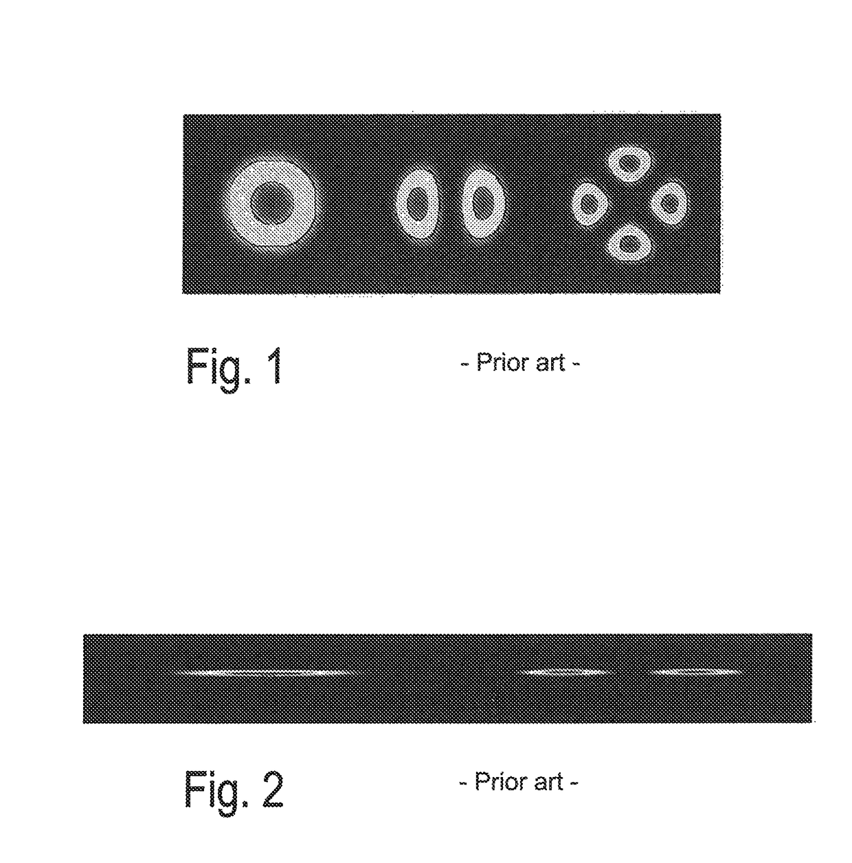
[0053]In the following, the LPrφmodes in TE and TM polarization, typically found in the literature, are used as an example of fiber modes (without limiting the general validity of the solution), whereas the terms TExy and TMxy are used for modes in the integrated optical circuit. FIGS. 1 and 2 show examples of such known modes.

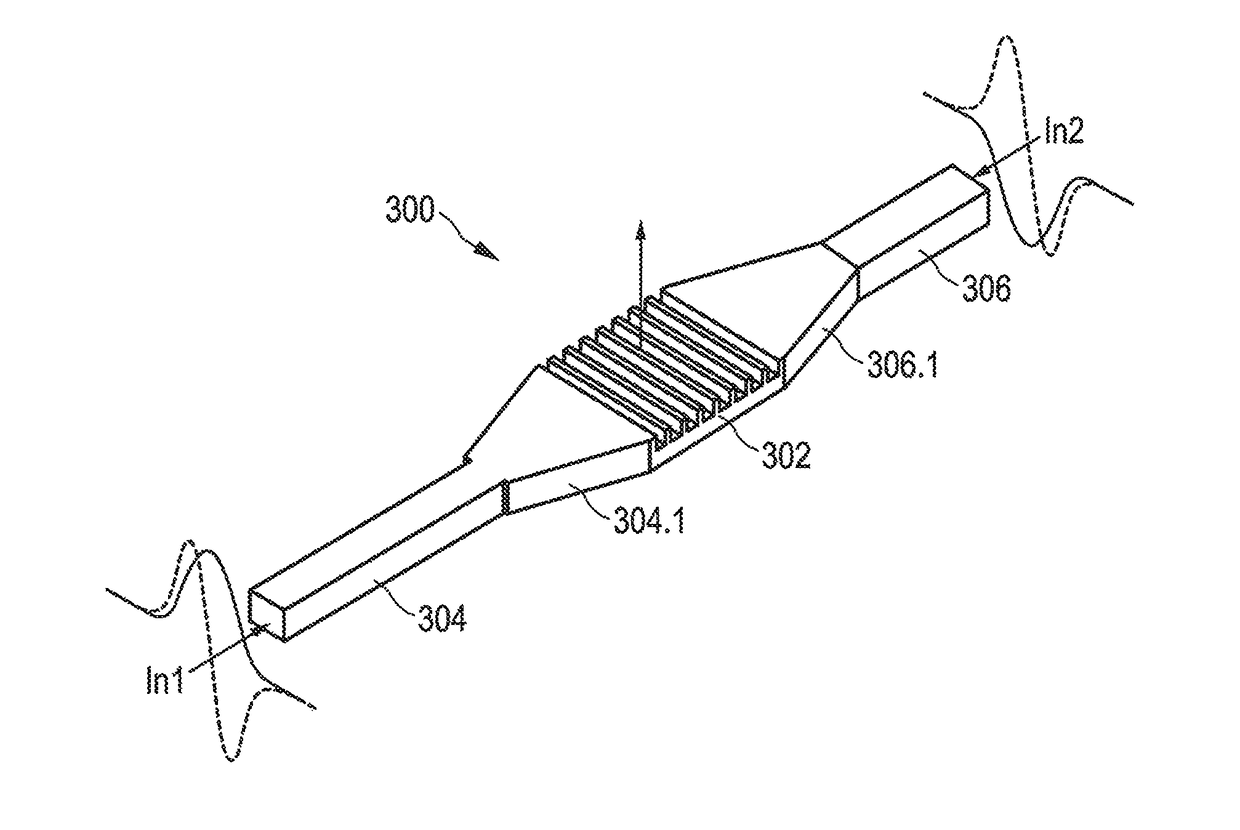
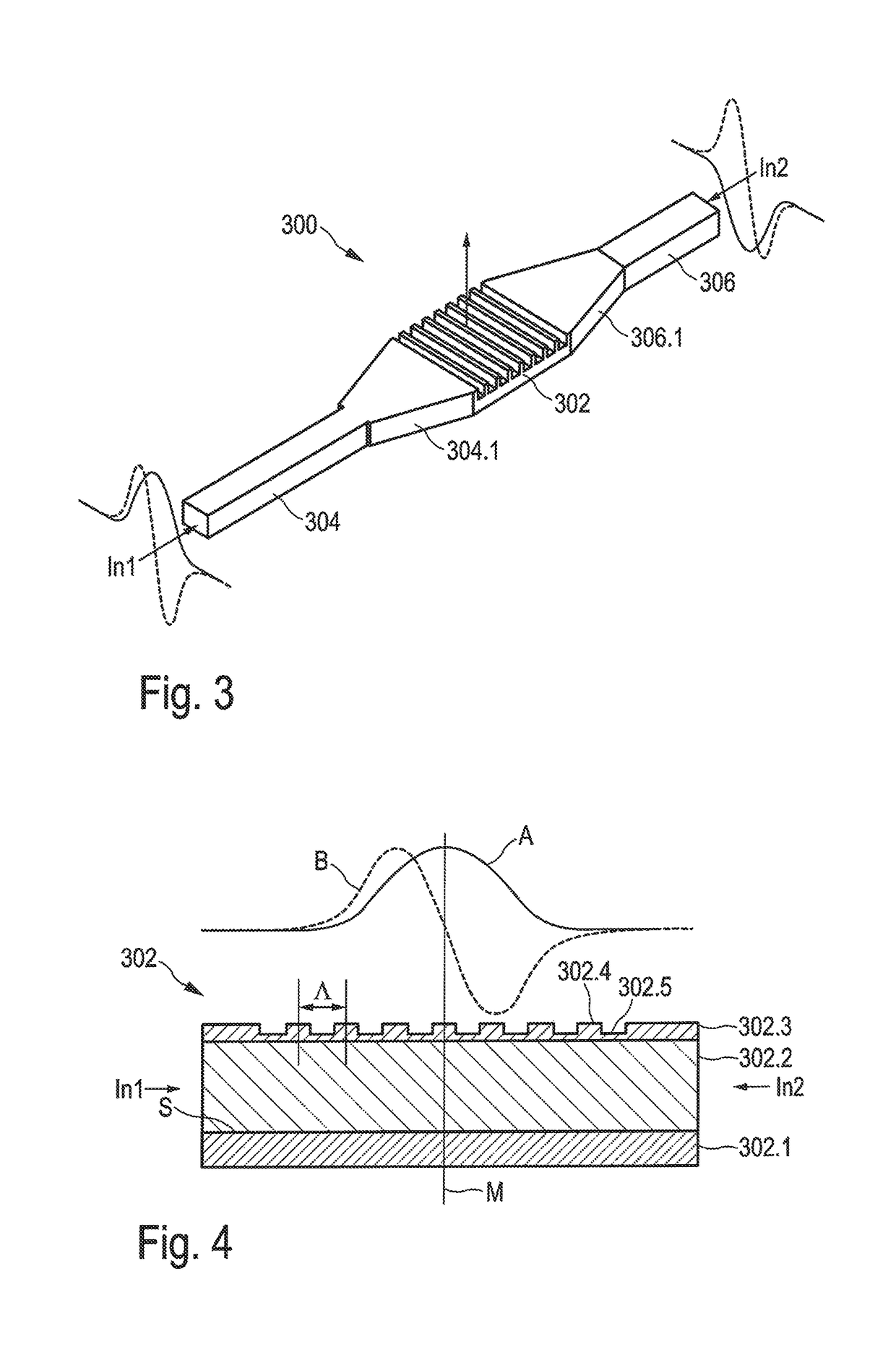
[0054]One embodiment of a coupler device 300 according to the invention is shown in FIG. 3. FIG. 4 shows a schematic cross-sectional view of the coupling grating in FIG. 3, in a plane containing a line from input In1 to input In2. The following description refers to both these figures in parallel.

[0055]An integrat...


PUM


Abstract

An integrated optical coupler device comprising, on a substrate surface: an integrated optical coupling grating extending in lateral directions parallel to the substrate surface and which, by diffraction at its grating structures, either converts electromagnetic waves, guided parallel to the substrate surface, of at least two waveguide modes of integrated optical waveguides into fiber modes propagating perpendicularly to the substrate surface, or converts electromagnetic waves, propagating perpendicularly to the substrate surface, of a fiber mode into electromagnetic waves, propagating parallel to the substrate surface, of at least two waveguide modes, and a first conductor pair, connected to the coupling grating and formed by a first and a second integrated optical waveguide, through which, in mutually opposite first and second directions parallel to the substrate surface, electromagnetic waves of at least two waveguide modes can be conducted to the coupling grating or can be conducted away from the coupling grating.

Description

CROSS REFERENCE TO RELATED APPLICATIONS[0001]This application is the U.S. National Stage of International Application Number PCT / EP2014 / 054079 filed on Mar. 3, 2014 which application claims priority under 35 USC § 119 to German Patent Application No. 102013203581.0 filed on Mar. 1, 2013 and German Patent Application No. 102013212752.9 filed on Jun. 28, 2013. Each of these applications are hereby incorporated by reference in their entirety.TECHNICAL FIELD[0002]The invention relates to an integrated optical coupler device, more particularly for use as a coupling interface between integrated optical waveguides and an optical multimode fiber.BACKGROUND OF THE INVENTION[0003]The only degree of freedom that has not yet been exploited for data transmission in fiber-optic systems is the spatial dimension, which is why space-division multiplexing (SDM) is currently the subject of numerous investigations. Space-division multiplexing includes not only the transmission of data in one fiber havi...

Claims


Application Information

Patent Timeline
Patent Type & Authority Patents(United States)
IPC IPC(8): G02B6/12G02B6/30G02B6/14G02B6/124G02B6/293G02B6/26
CPCG02B6/268G02B6/124G02B6/14G02B6/29323G02B6/30G02B2006/12152G02B2006/12159
Inventor WOHLFEIL, BENJAMINZIMMERMANN, LARS
Owner IHP GMBH INNOVATIONS FOR HIGH PERFORMANCE MICROELECTRONICS LEIBNIZ INST FUR INNOVATIVE
Why Eureka
Try Eureka