Battery life of portable electronic devices

a portable electronic device and battery life technology, applied in the direction of emergency power supply arrangements, transportation and packaging, transmission, etc., can solve the problems of inoperable foregoing devices, burden on users, and effectively turning unusable, and achieve the effect of enhancing the battery life of such devices

Active Publication Date: 2018-06-19
ENERGOUS CORPORATION
View PDF865 Cites 65 Cited by
  • Summary
  • Abstract
  • Description
  • Claims
  • Application Information

AI Technical Summary

Benefits of technology

[0005]The present disclosure provides a method for improving battery life of electronic devices running on small batteries, for example coin batteries. The method may include wireless power transmission through suitable techniques such as pocket-forming, while including receivers and capacitors in the aforementioned devices.
[0006]In a system for wireless power transmission to improve battery life in a portable electronic device, comprising: a transmitter for generating RF waves having at least two RF antennas to transmit the generated RF waves through the antennas in constructive interference patterns; a micro-controller within the transmitter controlling the constructive interference patterns of generated RF waves to form pockets of energy in predetermined areas or regions in space; a receiver embedded within the portable electronic device with at least one antenna to receive the pockets of energy in the predetermined regions in space; a micro-controller within the receiver for communicating the power requirements of the portable electronic device to the micro-controller in the transmitter; and an auxiliary power supply within the receiver having a parallel connection to a main power supply in the portable electronic device wherein the auxiliary power supply is charged by the pockets of energy.
[0012]The method here disclosed may provide wireless power to electronic devices such as headsets, smart-watches and the like. As described in embodiments above, such devices may include a capacitor or other suitable charge-storing devices, which upon discharge may power fully and / or partially the aforementioned devices. The foregoing method may decrease fully and / or partially power loads on a device's battery. Thus, battery life in such devices may be enhanced.

Problems solved by technology

When batteries run out, the foregoing devices may be inoperable and can effectively turn unusable.
This may be a burden for users which may need to carry extra batteries, whenever they go out, in case the aforementioned electronic devices run out of power.
In the worst case scenario, batteries in such devices may not be replaceable.
Thus, these devices may no longer be useful and may therefore be disposed as waste.
This may have cost implications as well as environmental implications because users may not only have to re-purchase items, but also produce waste which may pollute the environment.

Method used


Image

  • Battery life of portable electronic devices
  • Battery life of portable electronic devices
  • Battery life of portable electronic devices

Examples


Embodiment Construction

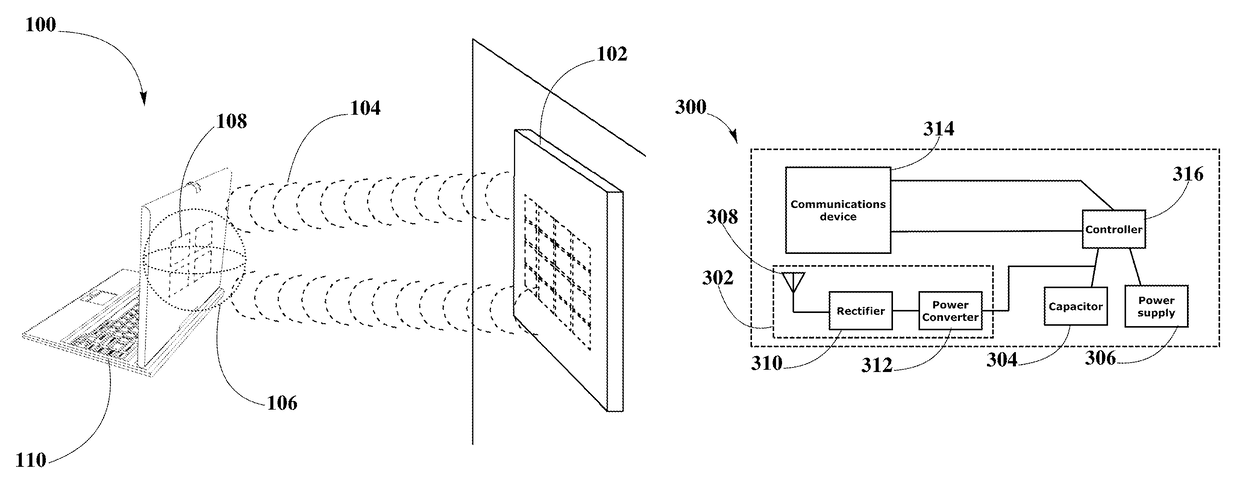
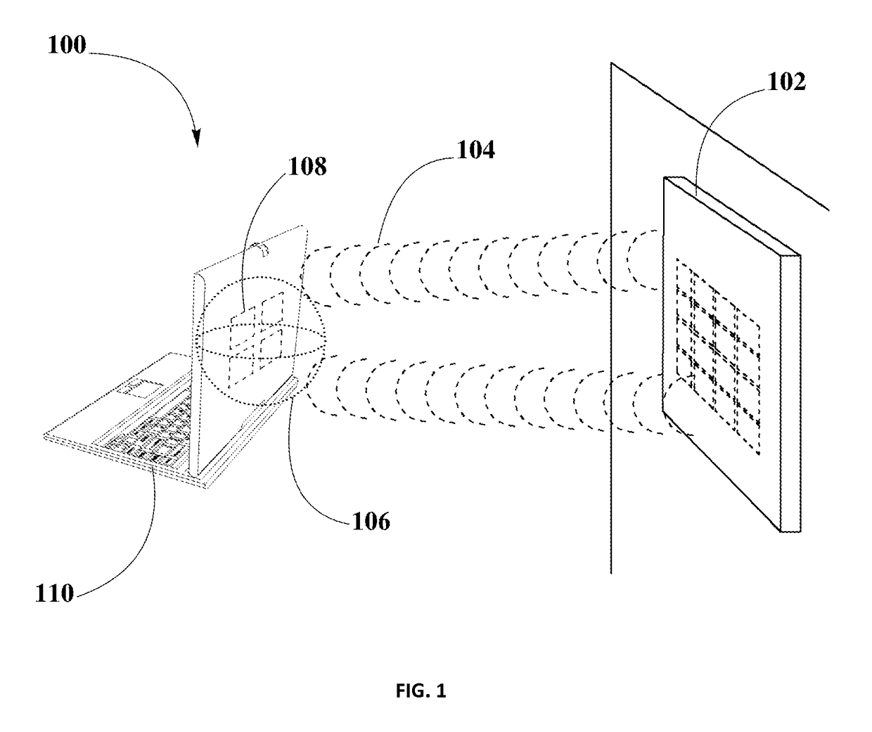
[0020]“Pocket-forming” may refer to generating two or more RF waves which converge in 3-d space, forming controlled constructive and destructive interference patterns.

[0021]“Pockets of energy” may refer to areas or regions of space where energy or power may accumulate in the form of constructive interference patterns of RF waves.

[0022]“Null-space” may refer to areas or regions of space where pockets of energy do not form because of destructive interference patterns of RF waves.

[0023]“Transmitter” may refer to a device, including a chip which may generate two or more RF signals, at least one RF signal being phase shifted and gain adjusted with respect to other RF signals, substantially all of which pass through one or more RF antenna such that focused RF signals are directed to a target.

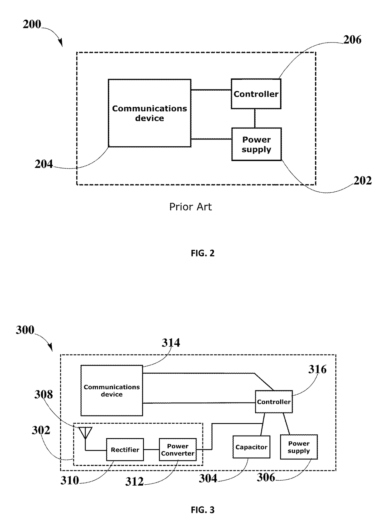
[0024]“Receiver” may refer to a device which may include at least one antenna, at least one rectifying circuit and at least one power converter for powering or charging an electronic device using RF w...


PUM


Abstract

The present disclosure provides a method for improving battery life of electronic devices such as Bluetooth headsets, smart-watches among others running on small batteries, for example coin batteries. The method may include wireless power transmission through suitable techniques such as pocket-forming, while including receivers and capacitors in the aforementioned devices. Wirelessly charged capacitors may provide sufficient power on which devices may run, and thus, battery life of such electronic devices may be enhanced.

Description

CROSS-REFERENCE TO RELATED APPLICATIONS[0001]This application is a continuation-in-part of U.S. patent application Ser. No. 13 / 919,567, filed on Jun. 17, 2013, which is herein fully incorporated by reference in its entirety.[0002]This application relates to U.S. patent application Ser. No. 13 / 891,430, filed May 10, 2013; U.S. Non-Provisional patent application Ser. No. 14 / 583,625, filed Dec. 27, 2014, entitled “Receivers for Wireless Power Transmission,” U.S. Non-Provisional patent application Ser. No. 14 / 583,630, filed Dec. 27, 2014, entitled “Methodology for Pocket-Forming,” U.S. Non-Provisional patent application Ser. No. 14 / 583,634, filed Dec. 27, 2014, entitled “Transmitters for Wireless Power Transmission,” U.S. Non-Provisional patent application Ser. No. 14 / 583,640, filed Dec. 27, 2014, entitled “Methodology for Multiple Pocket-Forming,” U.S. Non-Provisional patent application Ser. No. 14 / 583,641, filed Dec. 27, 2014, entitled “Wireless Power Transmission with Selective Range...

Claims


Application Information

Patent Timeline
Patent Type & Authority Patents(United States)
IPC IPC(8): H02J7/02H04B5/00
CPCH04B5/0037H02J7/025H04B5/0031H02J7/345H02J9/005H02J50/20
Inventor LEABMAN, MICHAEL A.BREWER, GREGORY SCOTT
Owner ENERGOUS CORPORATION
Why Eureka
Try Eureka