Fast FIR filtering technique for multirate filters

a filtering technique and filtering technology, applied in the direction of electrical equipment, digital technique networks, impedence networks, etc., can solve the problems of high sampling rate necessitated by these wideband signals, significant computational burden on the fpga which processes digital signals, and many traditional fir filter structures not directly applicabl

Active Publication Date: 2018-06-19
VECIMA NETWORKS
View PDF1 Cites 0 Cited by
  • Summary
  • Abstract
  • Description
  • Claims
  • Application Information

AI Technical Summary

Problems solved by technology

While this is very convenient from a system perspective, the higher sampling rates necessitated by these wideband signals place a significant computational burden upon the FPGA which processes the digital signal.
In many applications, the required sampling rate of the digital signal exceeds the maximum clock frequency of the FPGA, which means that many traditional FIR filter structures are not directly applicable.
The downside of the parallel FIR approach is its cost, which increases linearly with L. As the required sampling frequency increases, the number of parallel data streams becomes large, which can render even modest filtering operations computationally expensive.
One downside of the standard FFA algorithm is that it is not well-suited to the case where the filter coefficients are symmetrical.
However, when the FFA is applied to a symmetrical filter, most of the FFA's subfilters are not symmetrical, thereby negating much of the benefit of the FFA.
However, the T&C FFA was designed to handle only single rate FIR filters.
As a result, this critical filtering stage is typically relatively expensive in modern systems.
The reason both the standard and T&C basic FFA structures are used is that applying the T&C FFA on non-symmetrical filters does not produce symmetrical subfilters.
Thus, there is no benefit to the additional cost of the T&C FFA when decomposing any subfilters that are not symmetrical.

Method used


Image

  • Fast FIR filtering technique for multirate filters
  • Fast FIR filtering technique for multirate filters
  • Fast FIR filtering technique for multirate filters

Examples


Embodiment Construction

[0095]Sample rate converters are a special class of multirate FIR filters. Two main types of sample rate converters exist: interpolators and decimators. Since a decimator can easily be obtained by transposing the signal flow graph of an interpolator [14], the discussion which follows concentrates on interpolators.

[0096]The polyphase decompostion of a single-input 1-to-M interpolator [15] is expressed in the z-domain as shown below.

[0097]Y⁡(z)=⁢H⁡(z)⁢X⁡(zM)=⁢∑i=0M-1⁢⁢z-i⁢Hi⁡(zM)⁢X⁡(zM)=∑i=0M-1⁢⁢z-i⁢Yi⁡(zM),(13)

where

[0098]Hi⁡(zM)=∑j=0K-1⁢⁢hi+jN⁢z-jM

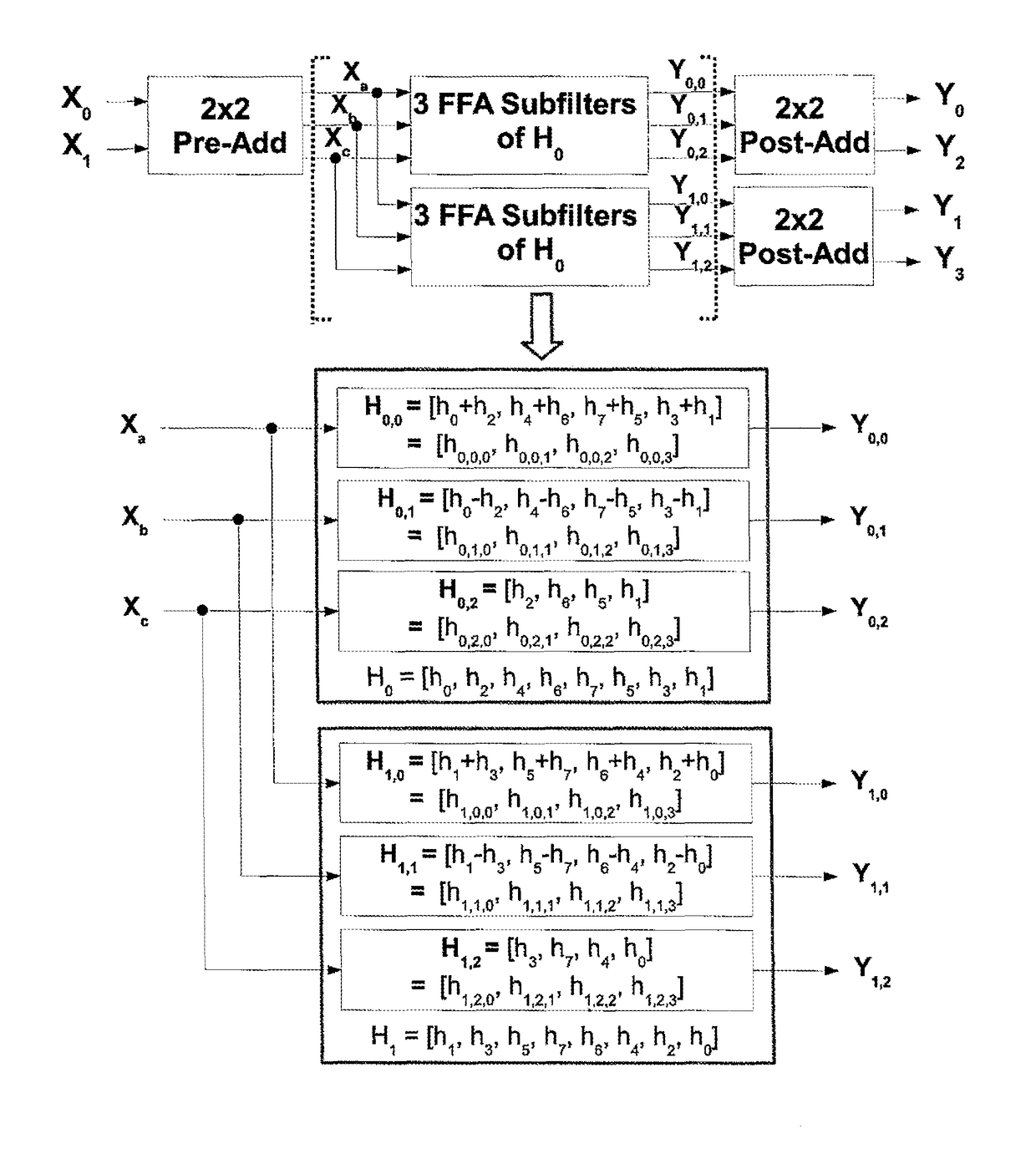
for N=KM. If the interpolator receives more than one input sample on every clock cycle, a specialized filter structure is required for the implementation. This paper proposes an FFA-based architecture that reduces the multiplier and adder requirements for symmetrical FIR sample rate converters. In the case of an L-parallel 1-to-M FFA based interpolator, the structure is developed as follows:

Step 1: Apply the polyphase decomposition techniqu...


PUM


Abstract

Data samples are filtered by using a digital filter where the length of an impulse response of the digital filter is finite, an impulse response of the digital filter is symmetric and the operation of the digital filter is multi-rate. The method uses a polyphase decomposition to break down the input data stream into N parallel substreams and the multi-rate digital filter is separated by a polyphase decomposition into multiple lower-rate sub-filters where each of the sub-filters is separated into a set of simpler sub-sub-filters which operate upon the same set of input samples and which have impulse responses which are jointly centro-symmetric, a set of pre-filtering arithmetic structures, and a set of post-filtering arithmetic structures and performing each such pair of sub-sub-filtering operations using a single shared filter structure, a set of pre-filtering combining adders, and a set of post-filtering separating adders.

Description

[0001]This application claims the benefit of priority under 35 USC 119 (e) of Provisional Application 62 / 051,555 filed Sep. 9, 2014.[0002]This invention relates to a method for filtering data samples using a digital filter to act upon an input data stream in order to transform it into an output data stream, where the length of an impulse response of the digital filter is finite, the impulse response of the digital filter is symmetric and the operation of the digital filter is multi-rate.BACKGROUND OF THE INVENTION[0003]The following references are related to this field and may provide information relevant to the subject matter herein so that the disclosures of each of the following documents are incorporated herein by reference:[0004][1] A. Oppenheim and R. Schafer, Discrete-Time Signal Processing. Pearson Education, 2011.[0005][2] F. Van de Sande, N. Lugil, F. Demarsin, Z. Hendrix, A. Andries, P. Brandt, W. Anklam, J. Patterson, B. Miller, M. Rytting, M. Whaley, B. Jewett, J. Liu, ...

Claims


Application Information

Patent Timeline
Patent Type & Authority Patents(United States)
IPC IPC(8): H03H17/06H03H17/02
CPCH03H17/0621H03H17/0275H03H2017/0247
Inventor BERSCHEID, BRIANMAYILAVELANE, AROUTCHELVAME
Owner VECIMA NETWORKS
Why Eureka
Try Eureka