
Method and device for controlling a temperature of steam for a steam power plant

a technology of steam power plant and temperature control, which is applied in the direction of steam engine plants, machines/engines, mechanical equipment, etc., can solve the problems of high influence of steam temperature to be controlled, not exceeded, and the maximum temperature limit of the boiler tube material supplied with steam, so as to achieve low cost and time-saving

Active Publication Date: 2018-07-03
SIEMENS ENERGY GLOBAL GMBH & CO KG
View PDF19 Cites 2 Cited by
  • Summary
  • Abstract
  • Description
  • Claims
  • Application Information

AI Technical Summary

Benefits of technology

This approach achieves precise and stable steam temperature control with reduced computational time and hardware costs, enabling faster commissioning and improved responsiveness to disturbances, while maintaining robustness and control quality.

Problems solved by technology

However, permissible maximum temperature limits of a boiler tube material supplied with the steam in the boiler and the turbine which is intended to be supplied with the steam must not be exceeded.
In addition, the steam temperature to be controlled is strongly influenced by numerous disturbances, such as e.g. load changes, soot blowing in the boiler, change of fuel, etc.
A precise temperature control of the steam is difficult to achieve for these reasons.
The disadvantage of the cascade control is that disturbances which affect the superheater itself can be compensated in the outer, slow circuit only, i.e. with low control quality.
The disadvantage of the two-circuit control is that a very large amount of time is required for an identification of parameters for the superheater model during a commissioning of the steam power plant.
However, since this plurality of steam states in the superheater which are used in an algorithm of the state control are not measurable, an observer circuit is required with which the required states are estimated.
However, such an algorithm of the state control responds highly sensitively to changes in a dynamic behavior of a control path in the state control.
Although very good control results are achieved e.g. in a load point of the steam power plant, only an insufficient control behavior is achieved under changed operating conditions of the steam power plant.
However, the LQG method used according to EP 2 244 011 A1 relates to linear regulation problems, whereas the injection mass flow, as the final manipulated variable of the inner control circuit, acts in a non-linear manner on the temperature controlled variable.
The online calculation of the regulator and observer matrix is associated with a very substantial computing time and storage space requirement.
It can therefore no longer run simultaneously with other automation functions on a standard automation processor.
It is thus necessary to provide additional automation processors which are, however, very expensive, or to use one or more separate PC modules, which are coupled into a control technology system of the steam power station.
The use of LQG control, as proposed according to EP 2 244 011 A1, is therefore associated with an additional cost for the hardware and corresponding spare parts procurement.
A derivative element of this type must be parameterized in plant tests, which is a time-consuming and costly process.

Method used


Image

  • Method and device for controlling a temperature of steam for a steam power plant
  • Method and device for controlling a temperature of steam for a steam power plant
  • Method and device for controlling a temperature of steam for a steam power plant

Examples


Embodiment Construction

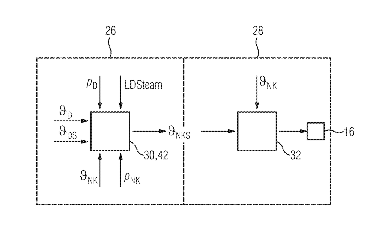
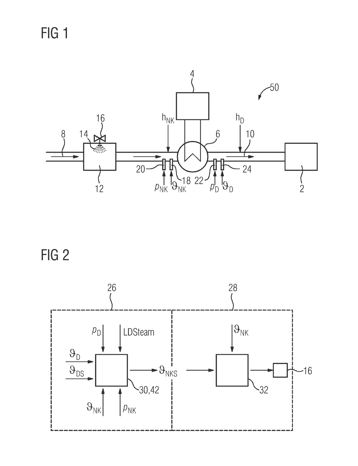
[0131]FIG. 1 shows a schematic representation of a cut-out from a steam power station 50 with a steam turbine as a steam power plant 2, a boiler 4 which delivers heat to a superheater stage, e.g. of a multistage superheater 6, through which steam 8 flows.

[0132]Due to the absorption of heat, the steam 8 in the superheater 6 is superheated to fresh steam 10 and is then fed to the steam turbine 2.

[0133]In order to regulate the temperature of the steam 8, a spray-type desuperheater 12 is provided which injects water 14 into the steam 8 and thus cools the latter. The quantity of the injected water 14 is set by a control valve 16.

[0134]A temperature sensor 18 and a pressure sensor 20 measure the temperature NK and the pressure pNK of the steam 8 upstream of the superheater 6, and a temperature sensor 22 and a pressure sensor 24 measure the fresh steam temperature D and the fresh steam pressure pD of the fresh steam 10 downstream of the superheater 6.

[0135]Merely in order to make a clearer...


PUM


Abstract

A method for controlling a temperature of steam for a steam power plant is provided. A state regulator controls the temperature of the steam at an outlet of a superheater using a feedback of multiple medium states of the steam in the superheater. An aim herein is to achieve a stable and precise control of the steam temperature. This is achieved in that the state regulator is a linear regulator, the feedback matrix of which is ascertained such that the regulator has the control quality of a linear-quadratic regulator.

Description

CROSS REFERENCE TO RELATED APPLICATIONS[0001]This application is the US National Stage of International Application No. PCT / EP2012 / 072844 filed Nov. 16, 2012, and claims the benefit thereof. The International Application claims the benefit of German Application No. DE 102011086562.4 filed Nov. 17, 2011. All of the applications are incorporated by reference herein in their entirety.FIELD OF INVENTION[0002]The invention relates to a method and a device for controlling a temperature of steam for a steam power plant in which a state regulator controls the temperature of the steam at an outlet of a superheater of the steam power plant with feedback of a plurality of medium states of the steam in the superheater.BACKGROUND OF INVENTION[0003]Steam power stations or steam power plants are widely known, for example from http: / / de.wikipedia.org / wiki / Dampfkraftwerk (available on Aug. 11, 2012).[0004]A steam power station is a type of power station for generating electricity from fossil fuels, ...

Claims


Application Information

Patent Timeline
Patent Type & Authority Patents(United States)
IPC IPC(8): F01K21/00F01K13/02
CPCF01K13/02F01K21/00
Inventor WENDELBERGER, KLAUS
Owner SIEMENS ENERGY GLOBAL GMBH & CO KG
Learn More