Splitter for air bleed manifold

a technology of air bleed manifold and splitter, which is applied in the cooling of turbine/propulsion engines, engine cooling apparatus, gas turbine plants, etc., can solve the problems of reducing the life of engine parts, and causing maximum temperature and lifting problems, so as to minimize the temperature gradient of jet engine parts

Active Publication Date: 2018-07-10
RTX CORP
View PDF15 Cites 0 Cited by
  • Summary
  • Abstract
  • Description
  • Claims
  • Application Information

AI Technical Summary

Benefits of technology

[0010]In still another aspect of the invention a method of minimizing the temperature gradients of jet engine parts is provided. The jet engine comprises an inner case circumferentially segmented into multiple inner case segments joined by inner case flanges and an outer case substantially concentric with the inner case. The outer case and inner case definine an air bleed manifold in which hot and cold air are mixed. The method comprises the step of: installing a splitter configured to direct the cold air into an inner cavity between the splitter and the inner case and across the inner case flanges and to direct the hot air into an outer cavity between the splitter and the outer case. The cold air may exit the inner cavity through openings disposed in an aft end of the splitter. The method may include the further step of using a circular deflector to deflect the hot air away from the openings. The deflector may also be used to direct the cold air into a radially outward flow path and into the outer cavity.

Problems solved by technology

These inner case flanges are subjected to significant stress during operation.
The hot air creates maximum temperature and lifting problems due to high temperature gradients and hot air mixing, which raises the steady state temperature of the inner case flanges, even when a heat shield is used.
As a result, the hot air can reduce engine part life, including the life of the inner case flanges.

Method used


Image

  • Splitter for air bleed manifold
  • Splitter for air bleed manifold

Examples


Embodiment Construction

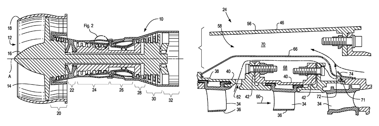
[0016]In the disclosure that follows certain relative positional terms are used such as “forward”, “aft”, “upper”, “lower”, “above”, “below”, “inner”, “outer” and the like. These terms are used with reference to the normal operational attitude of a jet engine and should not be considered otherwise limiting. The forward end of a jet engine generally refers to the air inlet end and the aft end generally refers to the exhaust end. Also, “radially outward” generally refers to a direction away from the engine center line while “radially inward” refers to a direction toward the engine center line.

[0017]A typical turbofan jet engine works by forcing compressed air into a combustion chamber where it is mixed with fuel and ignited so that the exhaust gases exit a downstream nozzle, thereby creating thrust.

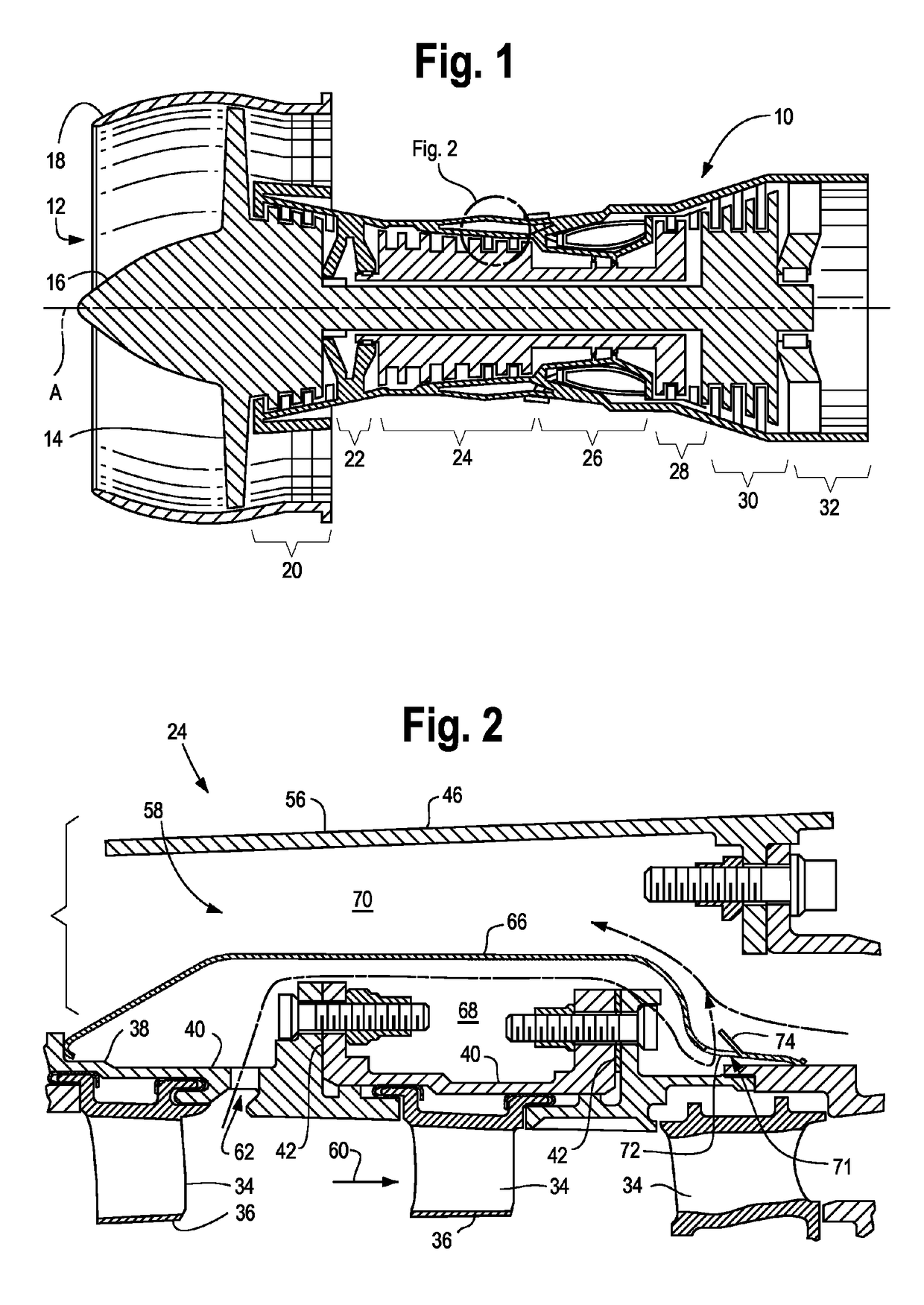
[0018]FIG. 1 is a longitudinal sectional view of an exemplary turbofan jet engine 10 that may be equipped with a split manifold according to the present disclosure. The engine 10 comprises ...


PUM

PropertyMeasurementUnit
temperatureaaaaaaaaaa
temperaturesaaaaaaaaaa
stressaaaaaaaaaa

Abstract

A splitter for protecting parts of a gas turbine engine is provided. The splitter segregates the flow of hot and cold gases into the air bleed manifold around the high compressor section to reduce maximum temperatures and minimize the temperature gradients of engine parts, especially inner case flanges The splitter divides the air bleed manifold into an annular inner cavity and an outer cavity. The splitter directs relatively cold air from the high compressor bleed ducts into the inner cavity and relatively hot air from the aft hub into the outer cavity, away from the inner case flanges.

Description

CROSS-REFERENCE TO RELATED APPLICATIONS[0001]This patent application is a 35 USC § 371 U.S. national stage filing of International Patent Application No. PCT / US13 / 76111 filed on Dec. 18, 2013, which claims priority under the 35 USC § 119(e) to U.S. Provisional Patent Application Ser. No. 61 / 783,596, filed on Mar. 14, 2013.FIELD OF THE DISCLOSURE[0002]The subject matter of the present disclosure relates generally to gas turbine engines. More particularly, the subject matter of the present disclosure relates to a splitter that segregates the flow of hot and cold gases in an air bleed manifold to reduce maximum temperatures and minimize the temperature gradients of engine parts, especially engine flanges, thereby prolonging engine part life.BACKGROUND OF THE DISCLOSURE[0003]Gas turbine engines, such as those used on jet aircraft, generally comprise an air intake port, a fan mounted on a hub near the air intake port and surrounded by a fan case which is mounted within an engine housing ...

Claims


Application Information

Patent Timeline
Patent Type & Authority Patents(United States)
IPC IPC(8): F02C7/18F01D25/24F02C6/08
CPCF02C7/18F01D25/243F02C6/08F01D25/246Y10T29/49828F05D2240/12
Inventor RIOUX, PHILIP ROBERTSAFTLER, RISHON
Owner RTX CORP
Why Eureka
Try Eureka