Insulated shipping containers

a technology for shipping containers and containers, applied in the field of shipping containers, can solve the problems of shortening the time that containers can maintain a refrigerated condition, creating temperature gradients or zones, and many problems of conventional insulated shipping containers, so as to reduce thermal convection, reduce temperature gradient, and improve the effect of temperature control

Active Publication Date: 2006-03-30
LIFOAM IND
View PDF27 Cites 1 Cited by
  • Summary
  • Abstract
  • Description
  • Claims
  • Application Information

AI Technical Summary

Benefits of technology

[0008] In accordance with the present invention, several embodiments of containers constructed of, for example; rigid polyurethane foam are described and shown herein and which are particularly useful for, among other purposes, small and large shipments, such as via air freight, including via LD3 shipping containers. Importantly, containers according to the present invention are basically formed of a bottom, preferably with a tray for holding product, four sides, and a lid, and preferably with a coolant tray. Furthermore, the bottom, sides and lid are designed to interlock (the sides and base preferably are slide locked or are tongue and grooved, as versus typical 45 degree corners that do not lock together or “grip” together), so as to reduce thermal convection. Also, preferably a rigid polyurethane foam is molded to form a bottom for the container and can have “pallet” grooves as distinguished from using wood which can invite termite problems, particularly in an air freight environment. The coolant tray preferably is a slide-in tray which contains a suitable coolant such as dry ice or gel packs, and which also is preferably made of rigid polyurethane foam and to maintain the coolant out of direct contact with the product. In addition, the interior walls and bottom of the container can be configured to provide a convection design to create a controlled air flow within the product compartment, and this air flow can reduce the temperature gradient within the product compartment and thus provide better and even temperature control when shipping biological and other products.
[0009] Thus, according to the concepts of the present invention, the containers can have gripping walls, particularly on larger containers, to reduce thermal convection between the outside environment and the internal environment. The sliding coolant tray can take any of many forms and / or shapes and is used to regulate the temperature between the coolant and the product. The interior walls of the sides, bottom, and top preferably are designed to provide convection and thus create a controlled air flow within the product compartment to control and reduce the temperature gradient within the product compartment, and thereby provide better control when shipping biological and other products. For example, the walls, bottom, and / or top can have shapes, such as grooves and / or protrusions, molded therein to provide convection and thus coolant air flow around the product load. Also, the side walls can have a shape such as a V or U shape or some variant thereof to provide “convection walls” on two sides, and coolant on the other two sides. Furthermore, a coolant tray can include a central pillar molded into the tray to keep the cooling effect of the coolant controlled in the center of the product load. Thus, containers according to the present invention provide control of thermal convection via predesigned air flow by the design of sides, grooves and the like to minimize the temperature gradient in the product load and in an attempt to maintain the same temperature at the corners, middle and at all areas of the product load. The gripping connection between the sides and base aid in controlling thermal conduction and convection from the outside to the inside of the container. The base is designed to maintain the product load off of the actual bottom of the container and is provided with air channels to allow internal air to circulate all around the load. The base for large containers is designed preferably to transport pallet loads of products such as biological products.

Problems solved by technology

Conventional insulated shipping containers have many problems, particularly when shipping temperature sensitive products for extended periods of time, such as when products are shipped internationally.
In addition, the cavity often includes airspaces around the product and coolant which can facilitate but not control convection, especially if the insulating material includes leaking seams.
Unfortunately, temperature gradients or zones are created.
These conditions may accelerate the melting of the coolant, consequently shortening the time that the container can maintain a refrigerated condition.
In addition, the cover may be formed from different material, such as polyester foam which may have a thermal resistance substantially lower than the body itself and thus may compromise the performance of the container.
Furthermore, the product and coolant typically are placed together within the cavity in a carton, which may have adverse effects.
Placing a coolant, such as loose blocks of dry ice, into a cavity against the product may inadvertently freeze and damage the product.
Even if held away from the product, the coolant may shift in the cavity during shipping, especially as it melts and shrinks in size, inadvertently contacting the product.
In addition, melted coolant may leak from its container, possibly creating a mess within the cavity or even contaminating the product being shipped.
Still, there are needs for containers particularly for shipping a large amount of product for long periods of time.

Method used


Image

  • Insulated shipping containers
  • Insulated shipping containers
  • Insulated shipping containers

Examples


Embodiment Construction

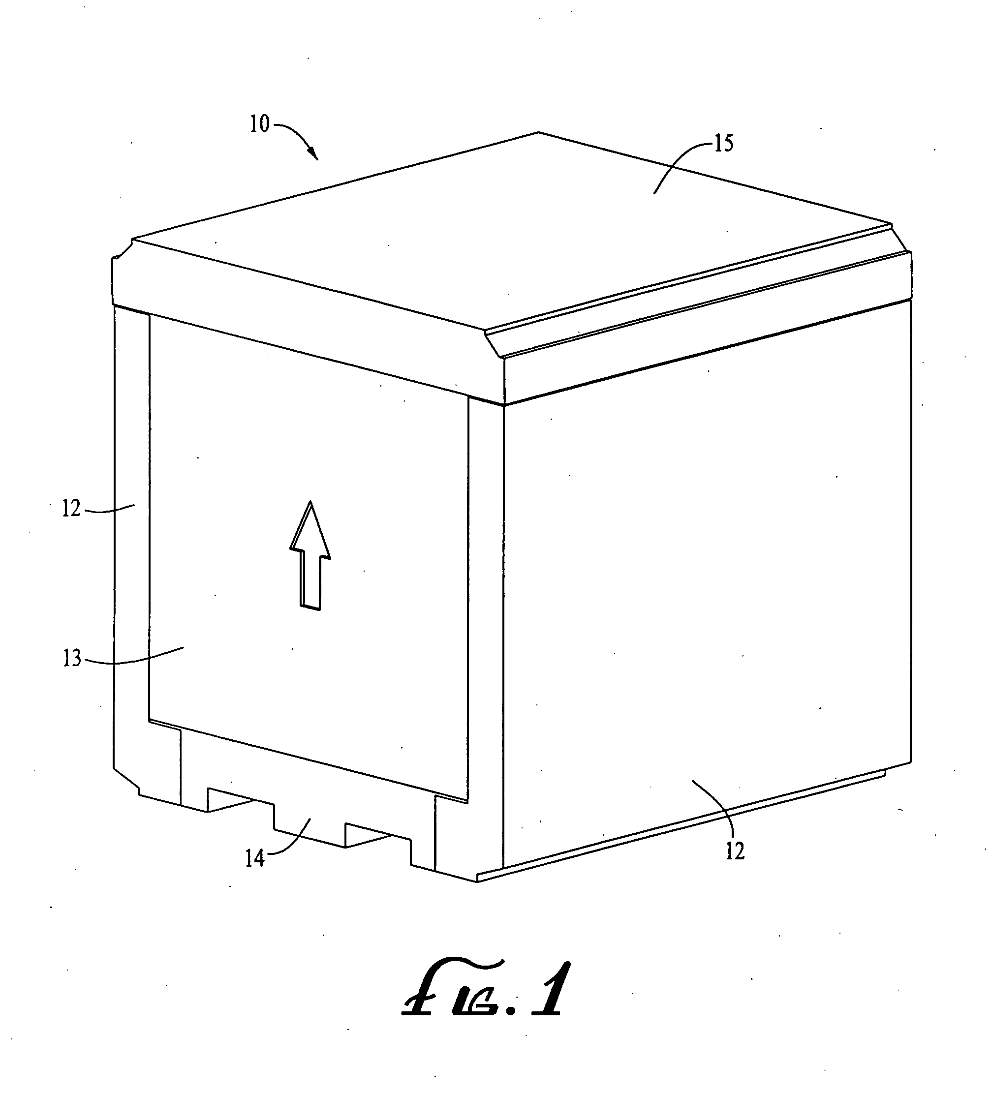
[0018] Turning now to the drawings, FIG. 1 illustrates one embodiment of an insulated container 10 according to the present invention. It preferably is constructed of water-based rigid polyurethane foam with sides 12, back of front 13, bottom 14 and lid or top 15 all with an interlocking design for easy storage and assembly, and, for reduction of convection.

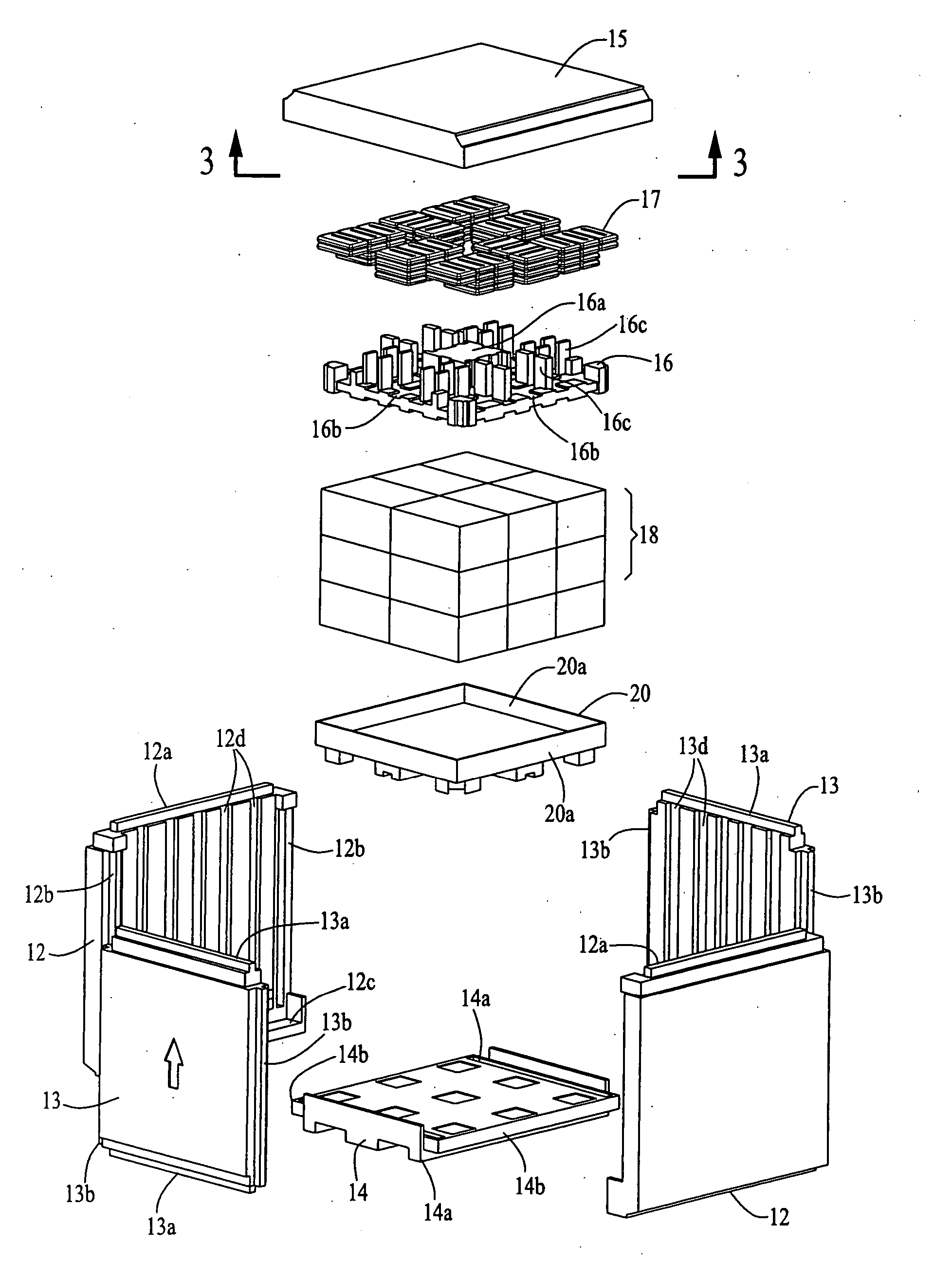
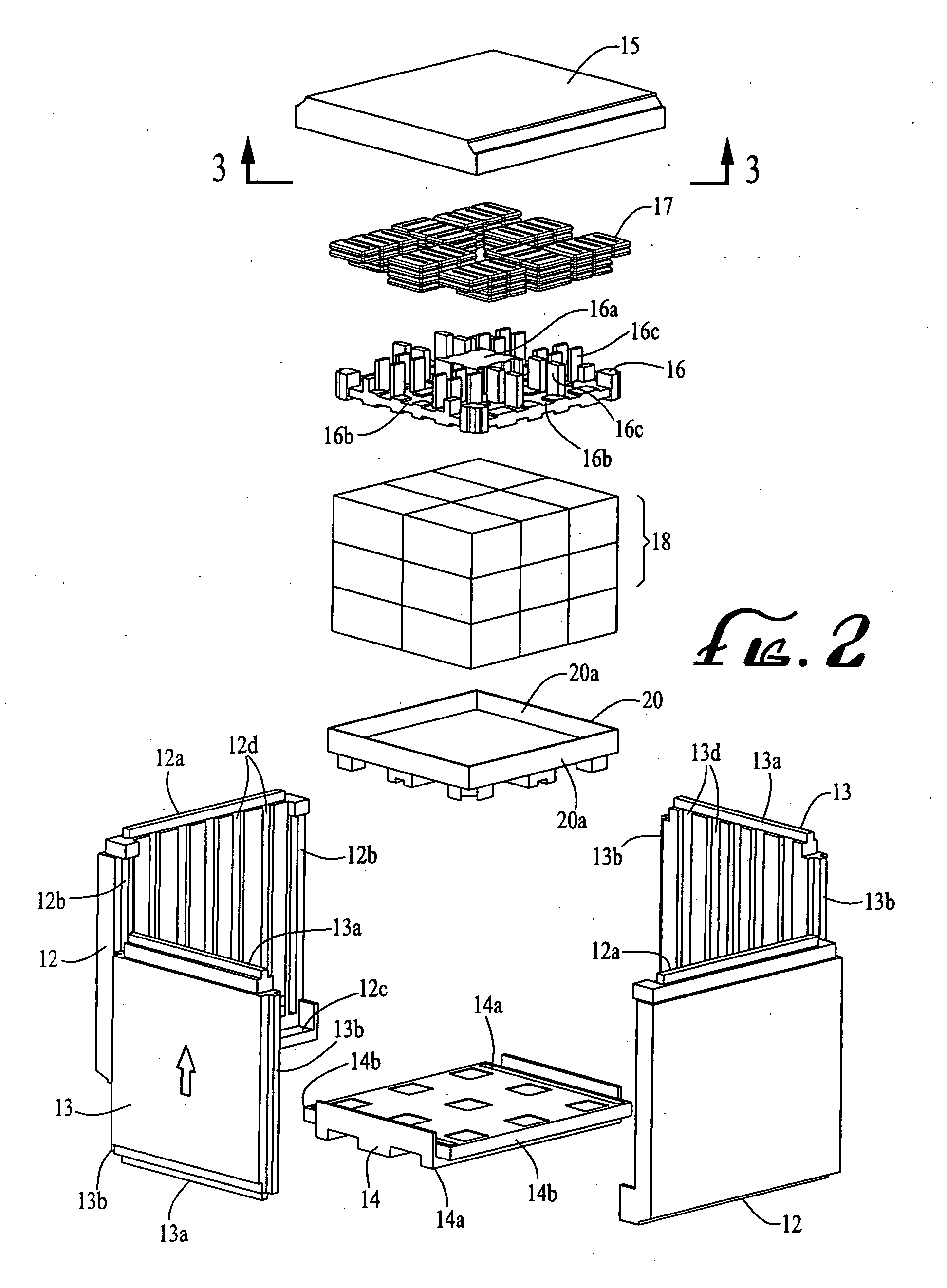
[0019] Turning to the exploded view of FIG. 2, a temperature range, for example, of 0° C. to 10° C. can be maintained by the use of an upper ice tray 16 to hold the necessary coolant 17 for the product load 18 in the container. The tray 16 can preferably be slid in on top of the product 18. An internal product tray 20 with built up sides 20a can be provided to insulate the bottom of the product load 18 from the bottom or base 14 and reduce the temperature gradient within the container. The bottom 14 of the container can include forklift grooves molded into the bottom thereof for eliminating the need for a separate wooden pallet....


PUM


Abstract

Shipping containers, and more particularly insulated shipping containers, for holding temperature sensitive products and coolant in a predetermined relationship to maintain a refrigerated or frozen condition for an extended period of time. Containers of this type can be molded from rigid polyurethane foam or other materials for shipping or transporting products such as biological and similar products which need to be maintained at 2° to 8° Centigrade or frozen. Specific constructions are shown and described.

Description

CROSS REFERENCE TO RELATED APPLICATIONS [0001] The present application is a continuation of co-pending application U.S. patent application Ser. No. 10 / 886,310 filed Jul. 7, 2004, which claims priority from U.S. provisional patent application Ser. No. 60 / 485,484 filed Jul. 7, 2003, the disclosure of which is fully incorporated herein by reference.FIELD OF THE INVENTION [0002] The present invention relates to shipping containers, and more particularly to insulated shipping containers for holding temperature sensitive products and coolant in a predetermined relationship to maintain a refrigerated or frozen condition for an extended period of time. For example, containers of this type are molded from rigid polyurethane foam or other materials for shipping or transporting products such as biological and similar products which need to be maintained at 2° to 8° Centigrade or frozen. BACKGROUND OF THE INVENTION [0003] Various type of shipping containers have been developed including convent...

Claims


Application Information

Patent Timeline
Patent Type & Authority Applications(United States)
IPC IPC(8): F25D3/08B65D81/38
CPCB65D81/3827F25D3/08F25D2331/804F25D2303/0844F25D2303/082
Inventor DERIFIELD, RODNEY
Owner LIFOAM IND
Why Eureka
Try Eureka