

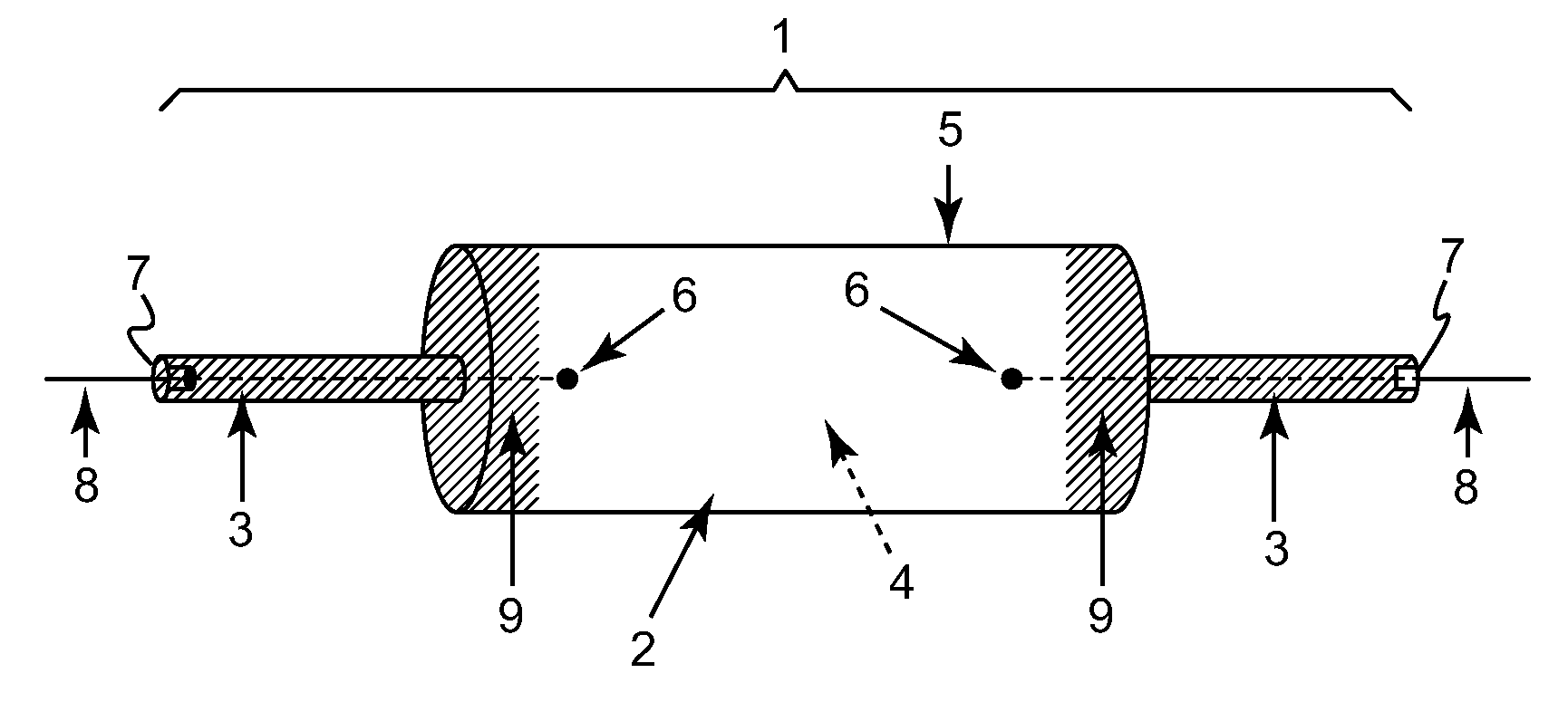
Thermal management of high intensity discharge lamps, coatings and methods
a technology of high-intensity discharge lamps and thermal management methods, which is applied in the manufacture of electric discharge tubes/lamps, discharge tubes luminescnet screens, electrode systems, etc., can solve the problems of shortening the lamp life, reducing the reliability of lamps, and high thermal loading, so as to improve thermal management and minimize temperature gradients in the vessel
- Summary
- Abstract
- Description
- Claims
- Application Information
AI Technical Summary
Benefits of technology
Problems solved by technology
Method used
Image

Examples
example 1
[0037]A detailed general experimental procedure used for coating an elongated ceramic HID lamp proximate its first and second end portions, is as follows:
[0038]Into a 250 mL polypropylene bottle was weighed 50 g YSZ (yttria-stabilized zirconia, 5 mm media, cylindrical). To this, was added 97 g deionized water, 5 g Darvan C (a polymethacrylate polyelectrolyte dispersant, trademark of R.T. Vanderbilt Co., Norwalk, Conn., USA), and 2 g of PEG 400 in sequences. Then 35 g of TiO2 (Ranbaxy, 98%, rutile form) was added to the above mixture. The resultant mixture was rack milled for 25 h to produce a slurry. A requisite amount of slurry was then transferred into a narrow glass vial so that the height of the slurry is adequate enough to cover a desired coating length on a lamp. A portion of a lamp leg to be coated was dipped into the slurry and then lifted out. Excess slurry was removed by holding the lamp in a vertical position. These steps of dip slurry coating and excess removal were repe...
example 2
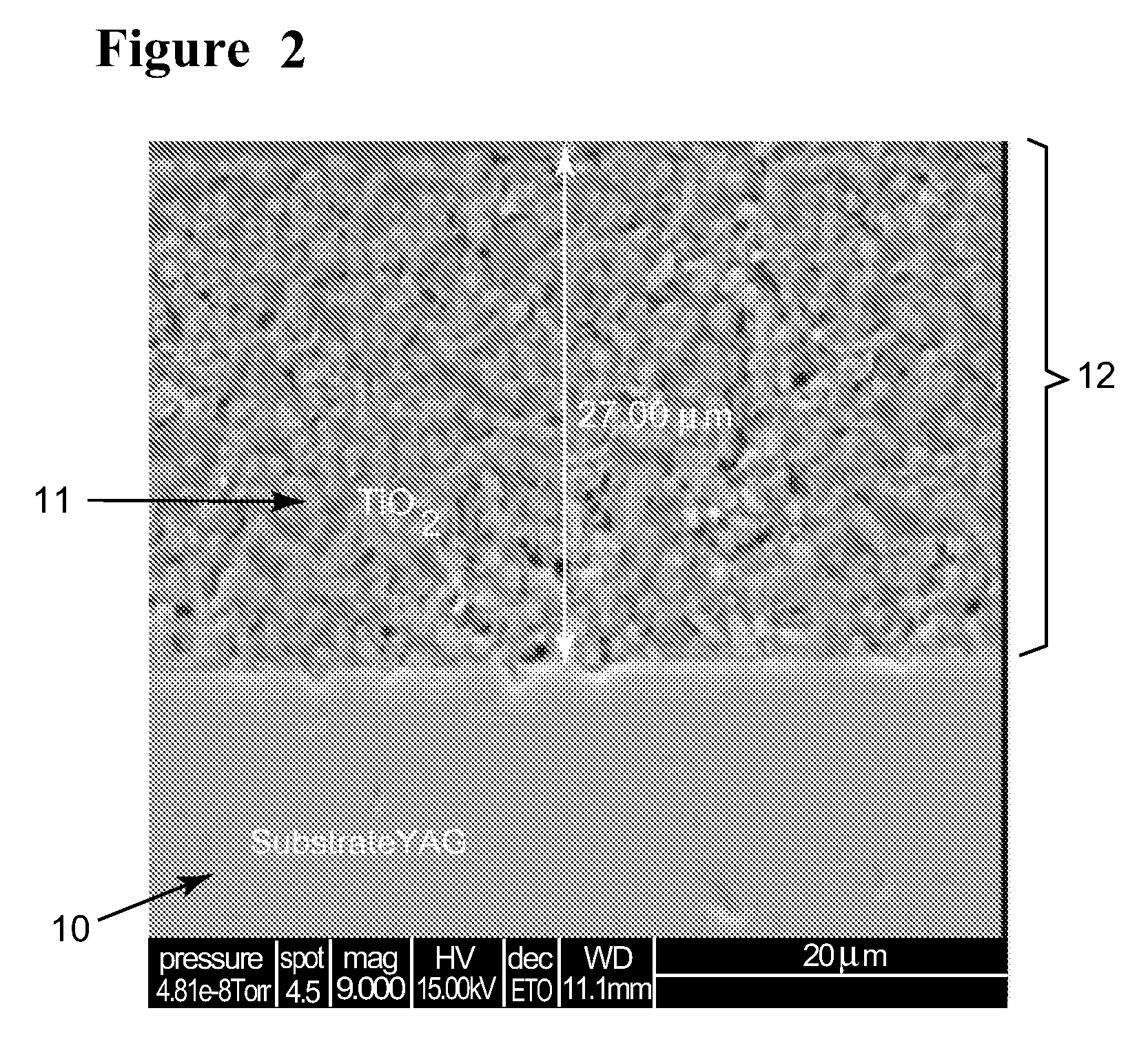
[0040]In this Example, YAG disks were utilized as model lamp envelope materials. In general, a procedure analogous to that of Example 1 was followed for coating these disks with titania. In particular for this example, the particle size distribution is shown in Table 1 below:
[0041]
TABLE 1Particle Size Distribution ofrutile TiO2 utilizedSpecific area61926(in cm2 / mLpowder)Median1.083particle size (inmicrons)Mean particle1.2801size (inmicrons)Standard0.7225deviation ofparticle size (inmicrons)
[0042]The median particle size of the powder used was approximately 1 micron, and the range was 0.3 to 1.3 microns. Aqueous slurries of this powder were prepared as in Example 1, but the slurry preparation conditions for crack free coatings were optimized by varying solids loading (TiO2 vol %) and suspension pH. An optimum slurry for providing crack-free coatings was found to be pH of about 9, solid loading at 9 vol % and milling for 24 h. In general, coating thickness on the YAG disk could be var...
example 3
[0045]One of the requirements a coating according to the present disclosure must meet is to survive the thermal cycling that happens during the lamp operations during start up and shut off. To simulate this, the coated YAG disks prepared in Example 2 were tested in a laboratory furnace at different temperatures. Thermal cycling tests were carried out at 1000° C. for periods of 30 min, 1 h, 2 h, and 500 h. In some cases, YAG disks with titania coatings above 20 micron thickness cracked and peeled off upon thermal cycling. Coating adherence after thermal cycling deteriorated further as the coating thickness went above 30 micron. It was found that the optimum coating thickness for good adhesion and reflectance is from about 5 to about 20 micron. After about 500 h of thermal cycling at 1000° C., reflectance of coatings within this range of layer thickness did not undergo deterioration.
PUM
| Property | Measurement | Unit |
|---|---|---|
| thickness | aaaaa | aaaaa |
| median size | aaaaa | aaaaa |
| temperature | aaaaa | aaaaa |
Abstract
Description
Claims
Application Information