Fuel Cell System and Stack

a fuel cell and stack technology, applied in the field of fuel cell systems, can solve the problems of insufficient application to the industry, slow reaction speed, and lowering stack performance, so as to reduce the temperature of the hot spot of the stack, reduce the temperature of the stack, and increase the electrochemical reaction speed

Inactive Publication Date: 2013-10-24
POHANG IRON & STEEL CO LTD
View PDF4 Cites 3 Cited by
  • Summary
  • Abstract
  • Description
  • Claims
  • Application Information

AI Technical Summary

Benefits of technology

[0035]According to the exemplary embodiment, the flowing directions of the fuel or the air between neighboring electricity generating units are formed to be different from each other, so that the hot spot formed at the inlet along the flowing direction of the air and the hot spot formed at the outlet are alternately formed along the laminated electricity generating units. Accordingly, the cold spots and the hot spots are alternately disposed to exchange heat so that the temperature gradient of the stack may be minimized.
[0036]Further, the temperature of the hot spot of the stack is lowered and the average temperature of the stack is raised to increase an electrochemical reaction speed which occurs in the fuel cell to maximize the performance of the stack.
[0037]Further, a phenomenon where a temperature of the stack is locally increased is prevented so as to prevent the life span of the stack from being shortened due to the deterioration.
[0038]Furthermore, the temperature gradient of the stack is minimized to enhance the reliability of the stack and improve the performance and the life span.

Problems solved by technology

An operating voltage of the electricity generating unit is generally 1.0 V or lower, which is insufficient to be applied to the industry.
As described above, if the temperature gradient is formed, the temperature of the hot spot in the electricity generating unit needs to be maintained to be lower than a heatproof temperature of not only the electricity generating unit, but also all components which configure the stack, such as a separating plate, a gasket, and a current collector, Therefore, the following problems occur.
Therefore, if the temperature of the other parts is lowered in order to manage the temperature of the hot spot of the stack below a predetermined temperature, an average temperature of the stack is lowered so that the reaction speed becomes slower, which lowers the performance of the stack.
Second, as the hot spot temperature of the stack is close to a heatproof temperature of any component, a deterioration speed of the component is accelerated, which may shorten the life span of the stack as a whole.
Third, if the temperature gradient is formed in the stack, a mechanical stress distribution is formed in the stack due to the difference in thermal expansion of each component, which may seriously affect the reliability of the stack such as unexpected destruction of a component or gas leakage.

Method used


Image

  • Fuel Cell System and Stack
  • Fuel Cell System and Stack
  • Fuel Cell System and Stack

Examples


Embodiment Construction

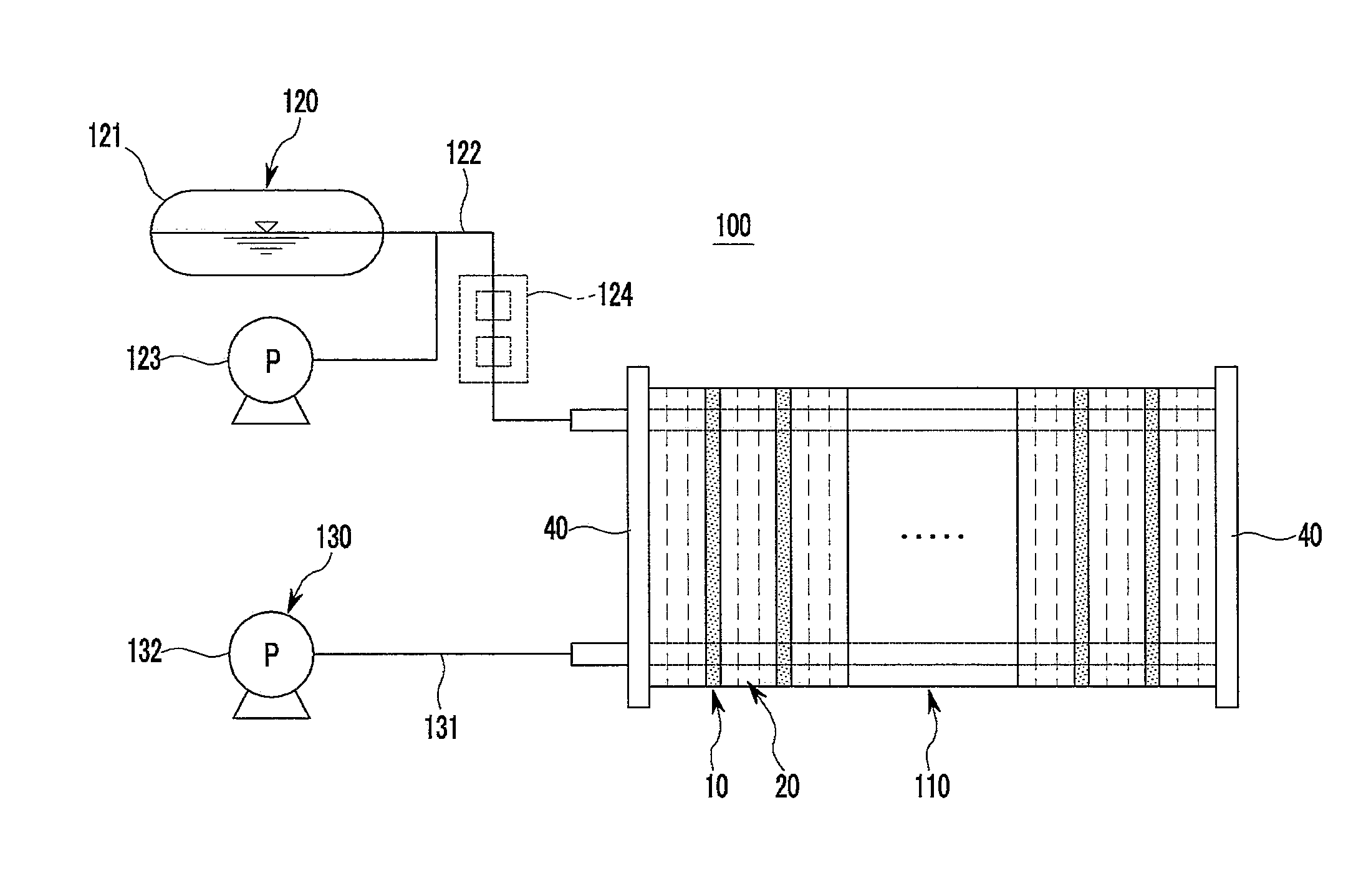
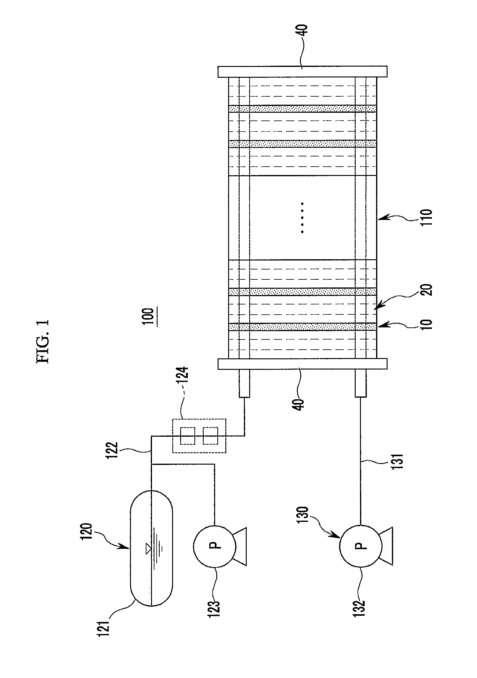
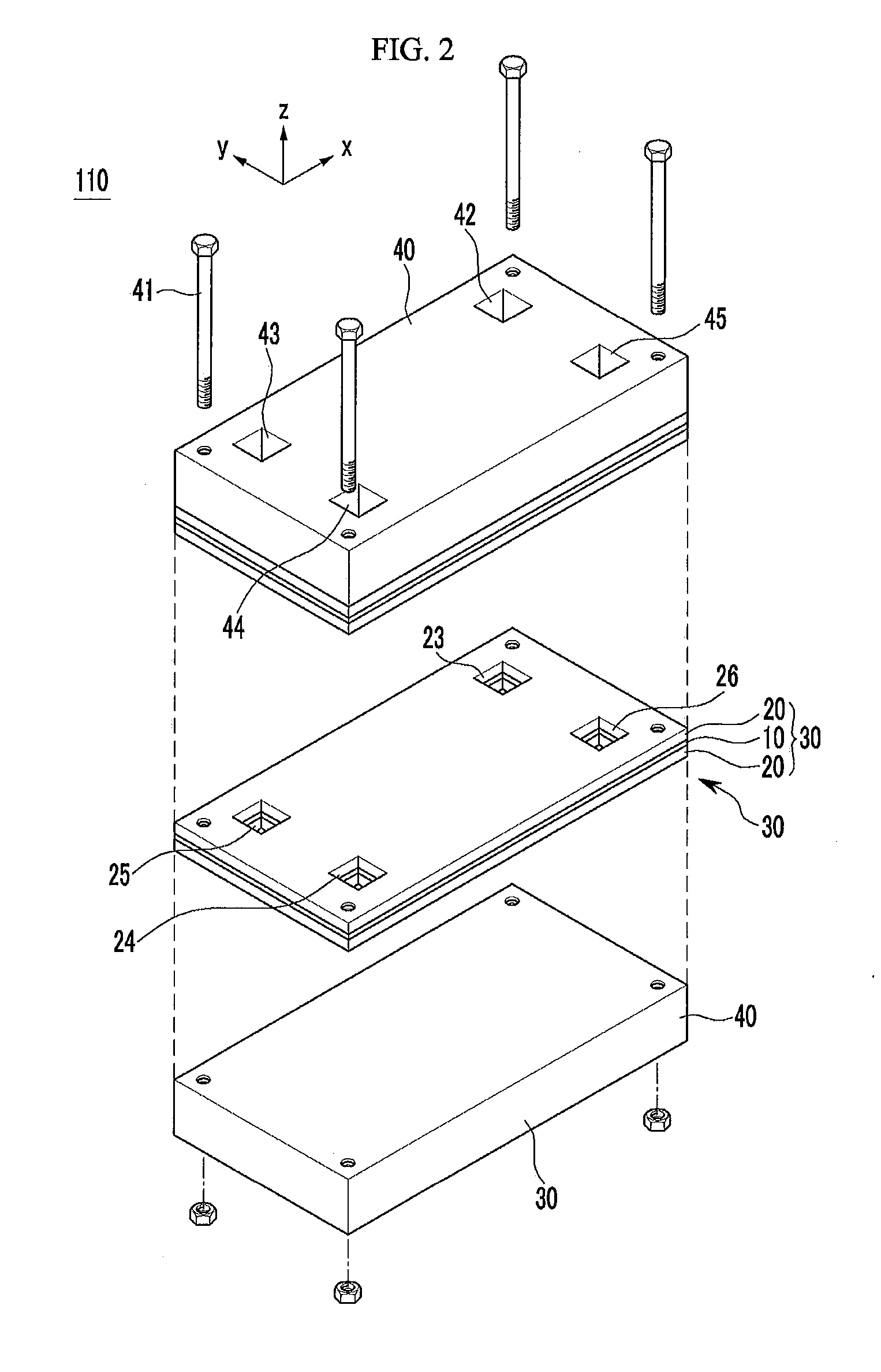
[0045]Hereinafter, the present invention will be described more fully hereinafter with reference to the accompanying drawings, in which exemplary embodiments of the invention are shown. Exemplary embodiments which will be described below will be modified in various different ways without departing from the spirit and the scope of the present invention, but the invention is not limited to the exemplary embodiments described herein.

[0046]It should be understood that the drawings are schematically illustrated but are not illustrated according to the exact scales. In addition, the relative size and ratio of each configuration shown in the drawings are arbitrarily illustrated for understanding and ease of description, and the thickness of layers, films, panels, regions, etc., are exaggerated or reduced for clarity. The arbitrary size is not restrictive but illustrative only. Further, the same reference numerals may denote the same structures, elements, or components shown in at least two...


PUM

PropertyMeasurementUnit
operating voltageaaaaaaaaaa
thicknessaaaaaaaaaa
electrical energyaaaaaaaaaa

Abstract

Provided is a fuel cell system in which a plurality of electricity generating units each including a unit cell in which an anode electrode and a cathode electrode are formed on both sides of an electrolyte film to use an electrochemical reaction of a fuel and an oxidizing agent to generate an electrical energy and a pair of separating plates which are disposed on both surfaces of the unit cell and have passages through which a fuel and an oxidizing agent are supplied to the anode electrode and the cathode electrode are laminated in which the electricity generating unit has a structure where a fuel flowing direction and/or a flowing direction of the fuel or the oxidizing agent are different between neighboring electricity generating units.

Description

BACKGROUND OF THE INVENTION[0001](a) Field of the Invention[0002]The present invention relates to a fuel cell system, and more specifically, to a fuel cell system and a stack which are capable of uniformizing internal temperature distribution.[0003](b) Description of the Related Art[0004]Generally, a fuel cell is an electric generator system which directly converts a chemical reaction energy of hydrogen and oxygen contained in a hydrocarbon based material or an air containing oxygen into an electric energy.[0005]For example, a solid oxide fuel cell is configured by a structure in which a plurality of electricity generating units including a unit cell which generates an electricity through an oxidation / reduction reaction of hydrogen and oxygen and a separating plate are laminated. The unit cell includes an electrolyte film, a positive electrode (cathode) which is disposed on one surface of the electrolyte film and a negative electrode (anode) which is disposed on the other surface of...

Claims


Application Information

Patent Timeline
Patent Type & Authority Applications(United States)
IPC IPC(8): H01M8/04
CPCH01M8/04201H01M8/04089H01M8/1213H01M8/2432H01M8/2483Y02E60/50H01M8/241
Inventor KIM, SEUNG GOOYANG, CHOONGMOKIM, DO HYEONGJUN, JOONG HWAN
Owner POHANG IRON & STEEL CO LTD
Why Eureka
Try Eureka