
Hybrid control method for an electrical converter

a converter and hybrid technology, applied in the direction of general control strategies, conversion with intermediate conversion to dc, efficient power electronics conversion, etc., can solve the problems of incorrect flux error and insufficient large disturbance, and achieve the effect of less switching loss, faster approach to estimated control variables, and more aggressive control

Active Publication Date: 2018-07-10
ABB (SCHWEIZ) AG
View PDF27 Cites 2 Cited by
  • Summary
  • Abstract
  • Description
  • Claims
  • Application Information

AI Technical Summary

Benefits of technology

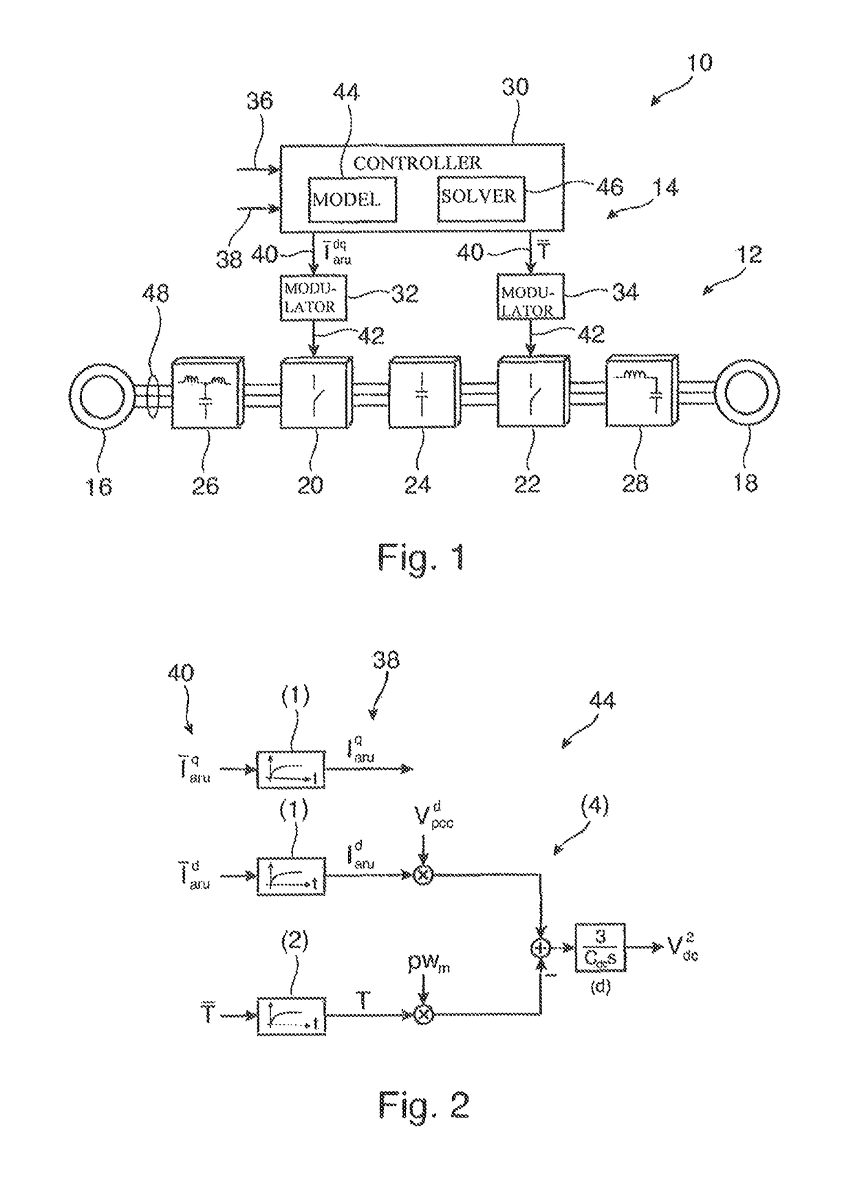
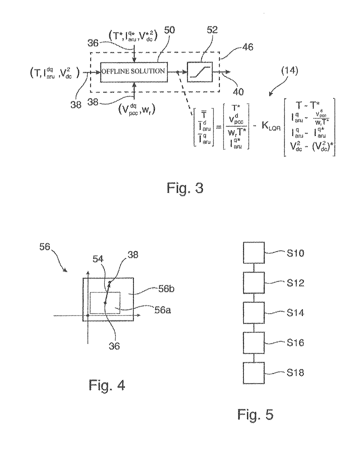
The invention provides a control method for an electrical converter that can maintain a constant energy level in the DC link, even when there are large disturbances in the source or load. The method is fast, reliable, and flexible, and it is based on optimal control. The method can switch between different control methods based on the control error, which allows for a faster and more flexible response to changes in the control variables. The control region can be selected from a normal mode control region and an emergency mode control region, depending on the energy level in the DC link. The method can slow down the electrical machine or prevent power flow when the energy level is low.

Problems solved by technology

However, this may be not sufficient for large disturbances.
However, in U.S. Pat. No. 6,219,237 B1, a flux error is correct always with the same method, i.e. with a corrective flux, which is determined from filters and / or regulators.

Method used


Image

  • Hybrid control method for an electrical converter
  • Hybrid control method for an electrical converter
  • Hybrid control method for an electrical converter

Examples


Embodiment Construction

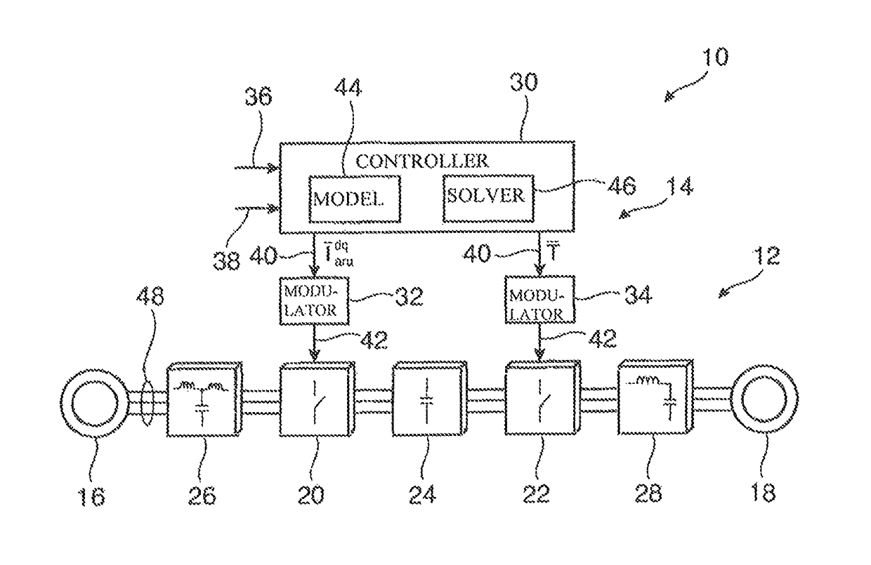
[0011]It is an objective of the invention to provide a control method for an electrical converter that can keep the energy stored in a DC link of an electrical converter at a constant level, also when comparable large disturbances on the source and / or load side appear. It is a further objective of the invention to provide a fast, reliable and flexible reacting control method for an electrical converter that is based on optimal control.

[0012]These objectives are achieved by the subject-matter of the independent claims. Further exemplary embodiments are evident from the dependent claims and the following description.

[0013]A first aspect to the invention relates to a method for controlling an electrical converter. The electrical converter may be a power converter adapted for processing current of more than 100 A and / or voltages of more than 1.000 V. In particular, the method may be used to control medium voltage and high voltage converters. In general, however, the control method may b...


PUM


Abstract

The present application is directed to an electrical converter having at least one of an active rectifier and an inverter interconnecting an electrical source with an electrical load. A method for controlling the electrical converter includes receiving at least one estimated control variable, receiving at least one outer loop control variable provided by an outer control loop and determining a control region based on a control error and selecting control parameters based on the control region. The control method then predicts at least one reference control value based on a solution of a physical model of the electrical converter. The solution is based on a constraint that minimizes a difference between the at least one estimated control variable and the at least one outer loop control variable. The control method then determines switching states of the electrical converter based on the reference control value.

Description

FIELD OF THE INVENTION[0001]The invention relates to the field of control of power converters. In particular, the invention relates to a method, a computer program, a computer-readable medium and a controller for controlling an electrical converter. Furthermore, the invention relates to a converter system comprising such an electrical converter.BACKGROUND OF THE INVENTION[0002]High power electrical motors are usually supplied by so-called medium voltage drives, which are used in various sectors to drive a variety of machines and processes. Such a medium voltage drive or an electrical converter may be characterised by the power flow between the load and a supplying grid and the energy storage provided by the DC link.[0003]In a usual setup, the electrical converter absorbs power from a three-phase AC power source (the electrical grid), stores this power as energy in DC form using capacitors or inductors (i.e. in the DC link), and finally converts this stored energy back to AC form and...

Claims


Application Information

Patent Timeline
Patent Type & Authority Patents(United States)
IPC IPC(8): H02M5/44H02M1/00H02M1/12
CPCH02M5/44H02M2001/0067H02M2001/0048H02M1/12H02M5/4585H02P23/0004H02M1/0067Y02B70/10H02M1/0048
Inventor AL-HOKAYEM, PETER
Owner ABB (SCHWEIZ) AG
Learn More