

Hybrid control method for an electrical converter
a converter and hybrid technology, applied in the direction of general control strategies, conversion with intermediate conversion to dc, efficient power electronics conversion, etc., can solve the problems of incorrect flux error and insufficient large disturbance, and achieve the effect of less switching loss, faster approach to estimated control variables, and more aggressive control
- Summary
- Abstract
- Description
- Claims
- Application Information
AI Technical Summary
Benefits of technology
Problems solved by technology
Method used
Image

Examples
Embodiment Construction
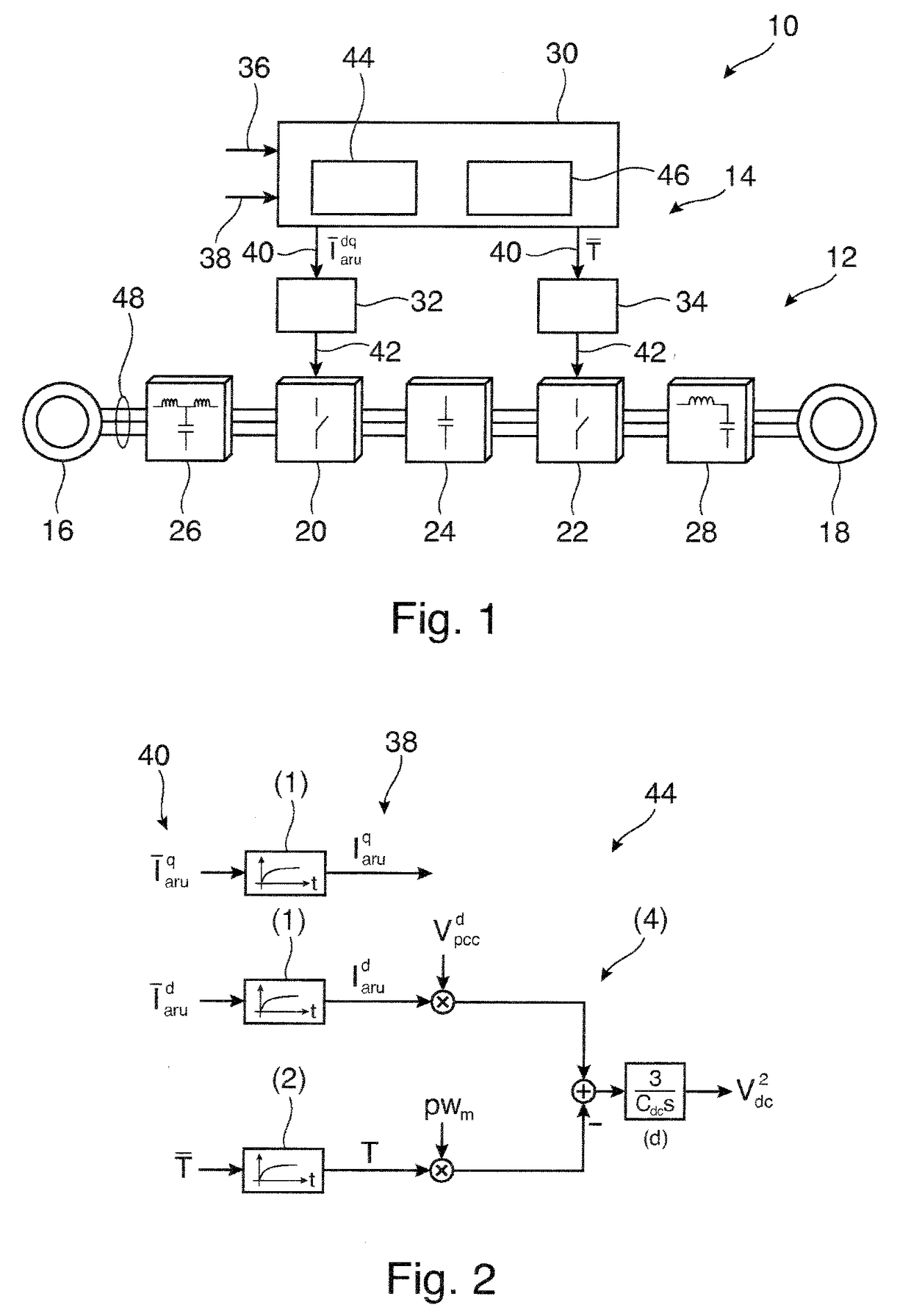
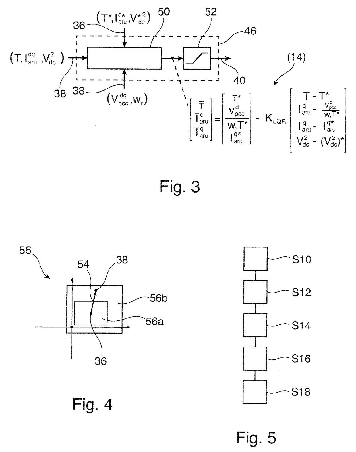
[0011]It is an objective of the invention to provide a control method for an electrical converter that can keep the energy stored in a DC link of an electrical converter at a constant level, also when comparable large disturbances on the source and / or load side appear. It is a further objective of the invention to provide a fast, reliable and flexible reacting control method for an electrical converter that is based on optimal control.
[0012]These objectives are achieved by the subject-matter of the independent claims. Further exemplary embodiments are evident from the dependent claims and the following description.
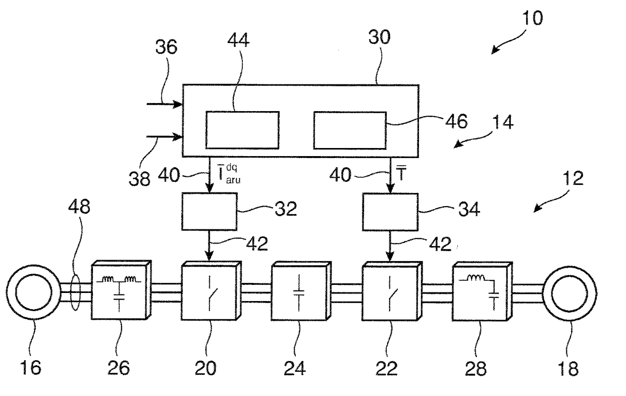
[0013]A first aspect to the invention relates to a method for controlling an electrical converter. The electrical converter may be a power converter adapted for processing current of more than 100 A and / or voltages of more than 1.000 V. In particular, the method may be used to control medium voltage and high voltage converters. In general, however, the control method may b...
PUM
 Abstract
Description
Claims
Application Information