Methods and devices for minimally-invasive delivery of radiation to the eye

a radiation delivery and eye technology, applied in the field of methods and devices for minimally-invasive delivery of radiation to the eye, can solve the problems of progressive damage to the retina, difficult or impossible to recognize faces, difficult or impossible reading, driving, etc., and achieve the effect of convenient and accurate placement of rbs and accurate localization of radiation over the targ

Active Publication Date: 2018-07-17
SALUTARIS MEDICAL DEVICES
View PDF283 Cites 3 Cited by
  • Summary
  • Abstract
  • Description
  • Claims
  • Application Information

AI Technical Summary

Benefits of technology

[0049]The present invention further features a “fine positioning” surgical technique. For example, after inserting a cannula into a potential space under a Tenon's capsule of the eye of the patient, the surgeon observes the position of (through the patient's pupil via a “visual axis”, see for example FIG. 5) the treatment position of the cannula in a posterior pole of the eye, and adjust it accordingly to accurately localize it over the target as shown in FIG. 5. In some embodiments, the physician observes the position of the treatment position and adjusts it while the patient's eye is in a primary gaze position. A primary gaze position is when the patient looks straight ahead. In some embodiments, the physician observes the position of the treatment position and adjusts it while the patient's eye is in any one of the following position: elevated, depressed, adducted, elevated and adducted, elevated and abducted, depressed and adducted, and depressed and abducted. By seeing the position of the treatment position, the surgeon can adjust the cannula to position the treatment position over a target, as shown for example in FIG. 5. In some embodiments, one of the advantages of the present

Problems solved by technology

ARMD attacks the center region of the retina (i.e., macula), responsible for detailed vision and damages it, making reading, driving, recognizing faces and other detailed tasks difficult or impossible.
In wet AR

Method used


Image

  • Methods and devices for minimally-invasive delivery of radiation to the eye
  • Methods and devices for minimally-invasive delivery of radiation to the eye
  • Methods and devices for minimally-invasive delivery of radiation to the eye

Examples


example 1

Surgical Technique

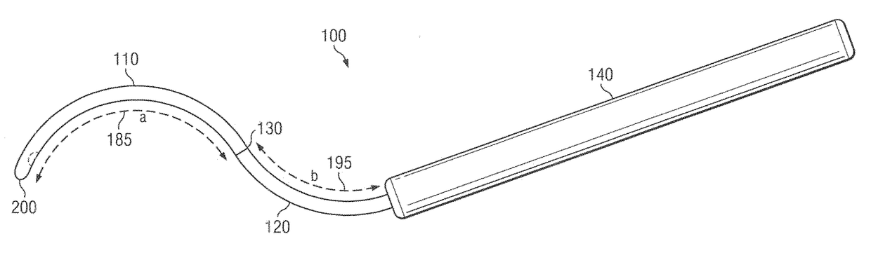
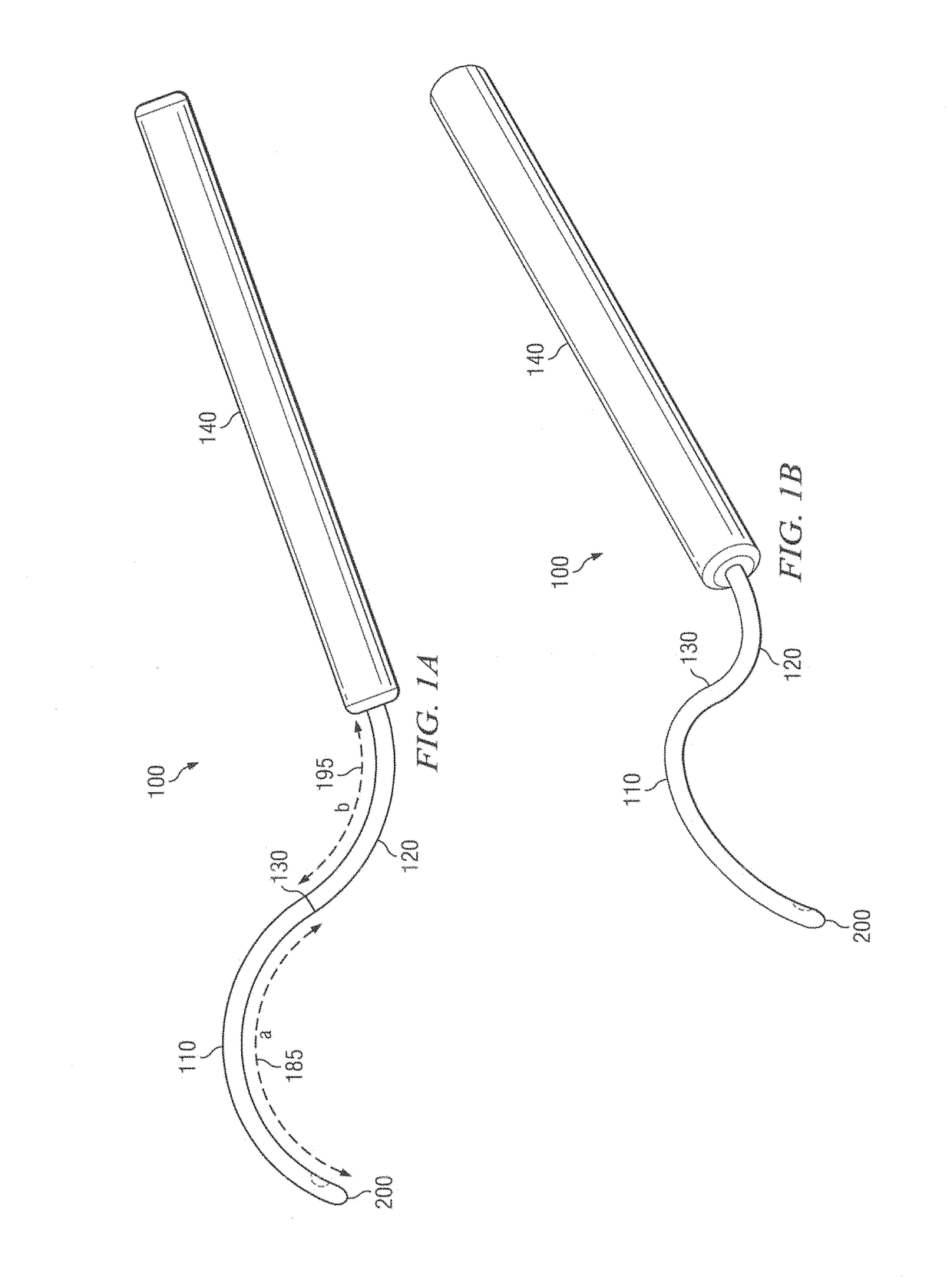
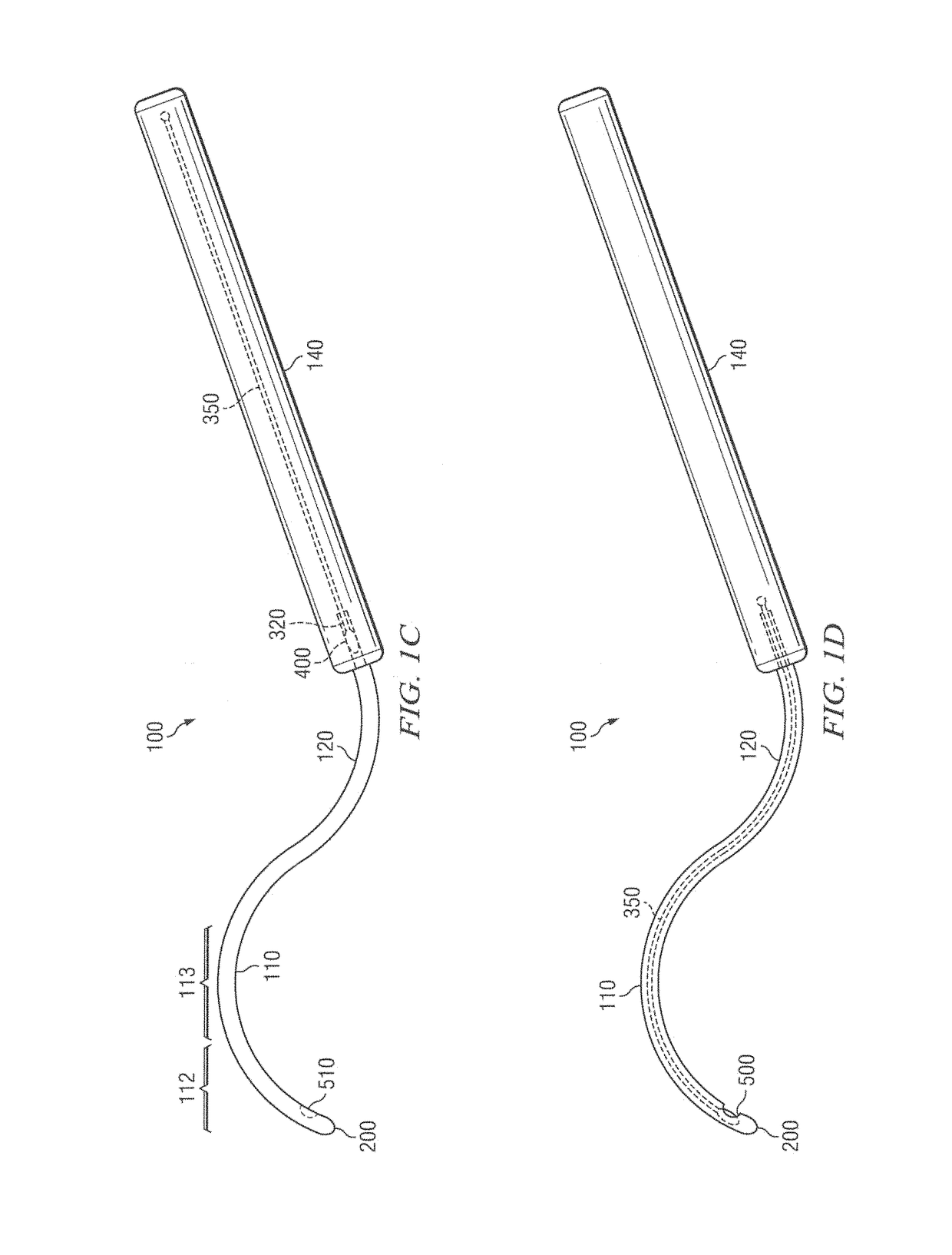
[0366]The following example describes a surgical procedure for use of the cannulae of the present invention. The eye is anesthetized with a peribulbar or retrobulbar injection of a short acting anesthetic (e.g., Lydocaine). A button hole incision in the superotemporal conjunctiva is preformed followed by a button hole incision of the underlying Tenon capsule 230.

[0367]If a cannula 100 comprising a distal chamber 210 is used, a small conjunctive peritomy (as large as the diameter of the distal chamber) is performed at the superotemporal quadrant. A Tenon incision of the same size is then performed in the same area to access the subtenon space.

[0368]Balanced salt solution and / or lydocaine is then injected in the subtenon space to separate gently the Tenon capsule 230 from the sclera 235.

[0369]The cannula 100 is then inserted in the subtenon space and slid back until the tip 200 is at the posterior pole of the eye. In some embodiments, the cannula 100 comprises a loca...

example 2

Fast Radiation Fall Off at the Edge of the Target

[0374]After the cannula is placed into position, an RBS is introduced to the sclera region on the eye ball that corresponds with the target (e.g., macula lesion) on the retina. Radionuclide of the RBS is Sr-90, and the RBS has a rotationally symmetrical exposure surface (e.g., circular) (see FIG. 14E). The exposure surface of the RBS has a diameter of about 3 mm. The target is 3 mm in diameter and is about 1.5 mm away from the exposure surface of the RBS.

[0375]As shown in FIG. 22, a target that is 1.5 mm away from the exposure surface has a radiation profile where the intensity of the radiation at the edge falls off significantly, i.e., there is a fast fall of at the target edge. When a shielding (deep wall, see FIG. 21) is employed, the radiation fall off at the edge is faster compared to when there is no shielding.

[0376]In this example, the ratio of the target diameter to the exposure surface diameter is about 1:1.


PUM


Abstract

Methods and devices for minimally-invasive delivery of radiation to the posterior portion of the eye including a cannula comprising a distal portion connected to a proximal portion and a means for advancing a radionuclide brachytherapy source (RBS) toward the tip of the distal portion; a method of introducing radiation to the human eye comprising inserting a cannula between the Tenon's capsule and the sclera of the human eye and emitting the radiation from the cannula.

Description

CROSS REFERENCE[0001]This application is a continuation in-part and claims benefit of U.S. patent application Ser. No. 13 / 953,528, filed Jul. 29, 2013, which is a non-provisional of U.S. Provisional Application No. 61 / 676,783, filed Jul. 27, 2012, the specification(s) of which is / are incorporated herein in their entirety by reference.[0002]This application is a continuation in-part and claims benefit of U.S. patent application Ser. No. 13 / 872,941, filed Apr. 29, 2013, which is a divisional of U.S. patent application Ser. No. 12 / 350,079, filed Jan. 7, 2009 and now U.S. Pat. No. 8,430,804, which is a non-provisional of U.S. Provisional Application No. 61 / 010,322, filed Jan. 7, 2008, U.S. Provisional Application No. 61 / 033,238, filed Mar. 3, 2008, U.S. Provisional Application No. 61 / 035,371, filed Mar. 10, 2008, and U.S. Provisional Application No. 61 / 047,693, filed Apr. 24, 2008, the specification(s) of which is / are incorporated herein in their entirety by reference.[0003]This applica...

Claims


Application Information

Patent Timeline
IPC IPC(8): A61M36/04A61N5/10
CPCA61N5/1017A61N5/1007
Inventor MARSTELLER, LAURENCE J.HAMILTON, RUSSELL J.BRIGATTI, LUCAVOEVODSKY, MICHAEL
Owner SALUTARIS MEDICAL DEVICES
Why Eureka
Try Eureka