Microfluidic devices and methods of their use

a microfluidic device and microfluidic technology, applied in the field of microfluidic devices, can solve the problems of loss of defined drops, problems downstream in detection and data analysis,

Active Publication Date: 2018-07-17
BIO RAD LAB INC
View PDF36 Cites 0 Cited by
  • Summary
  • Abstract
  • Description
  • Claims
  • Application Information

AI Technical Summary

Benefits of technology

[0027]In some embodiments, the method comprises introducing an emulsion comprising drops into the microfluidic channel and exposing the microfluidic channel to a first pressure; and moving the emulsion past the fluid communication with the relatively smaller channel(s), wherein the relatively smaller channels comprise an immiscible fluid continuous phase and are exposed to a second pressure and wherein the second pressure is higher than the first pressure such that the immiscible fluid continuous phase relatively smaller channel(s) moves from the relatively smaller channels to the microfluidic channel, thereby reducing the drop concentration in the emulsion in the microfluidic channel.

Problems solved by technology

As the newly injected drops flow throughout the microfluidic channels within the microfluidic device, the drops often mix and rearrange themselves, resulting in the loss of defined sets of drops, causing issues downstream in detection and data analysis.

Method used


Image

  • Microfluidic devices and methods of their use
  • Microfluidic devices and methods of their use
  • Microfluidic devices and methods of their use

Examples


examples

[0159]Although the present invention and its advantages have been described in detail, it should be understood that various changes, substitutions and alterations can be made herein without departing from the spirit and scope of the invention as defined in the appended claims.

[0160]The present invention will be further illustrated in the following Examples which are given for illustration purposes only and are not intended to limit the invention in any way.

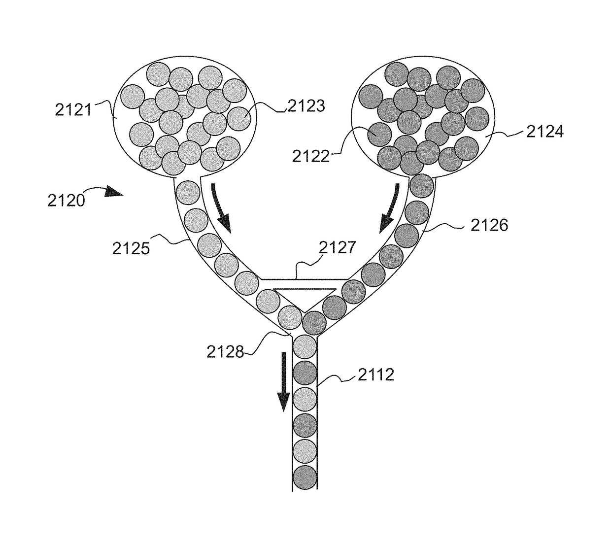
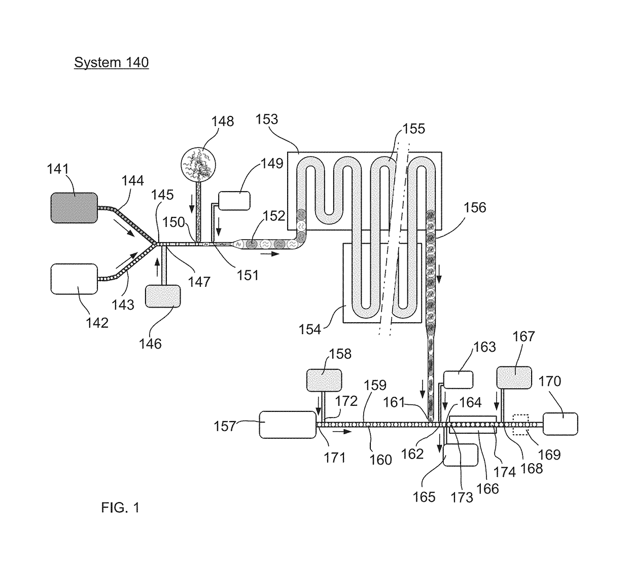
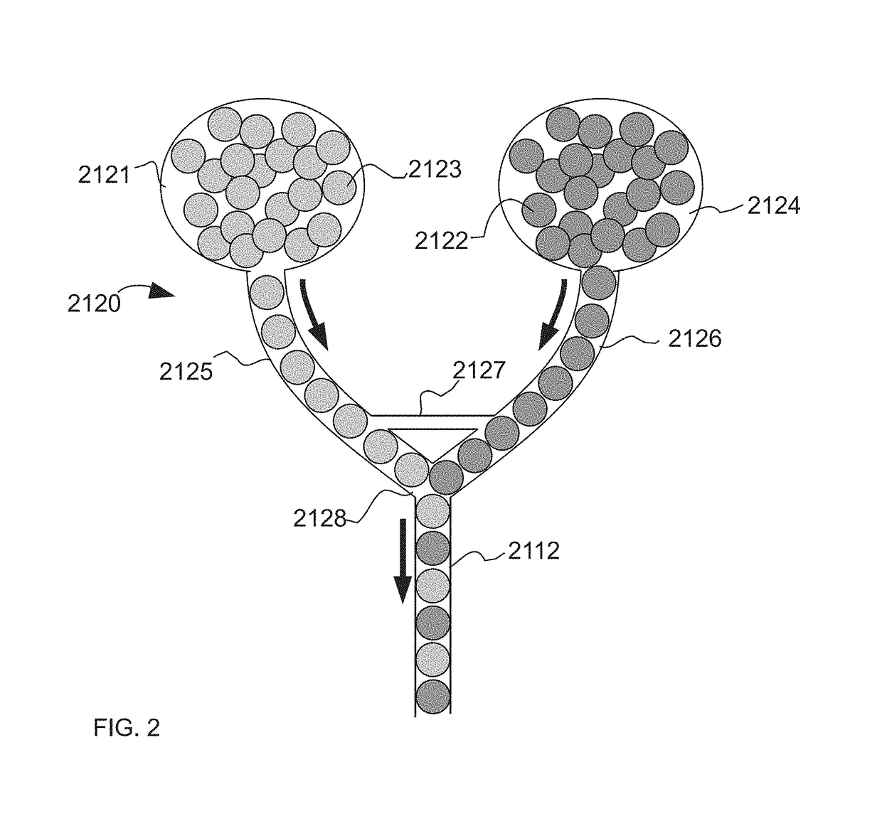
[0161]In one example, the present invention may be used to as part of a system (e.g., as depicted in FIG. 1) to perform methods for detecting the presence or absence of a particular nucleic acid sequence in a sample. A nucleic acid sample (148) may be injected into the system by the user. The system then injects this sample into a multitude of droplets (150), present within an emulsion, containing the reagents necessary for a polymerase chain reaction (PCR) amplification reaction. These droplets contain the appropriate oligonucleo...


PUM

PropertyMeasurementUnit
diameteraaaaaaaaaa
volumeaaaaaaaaaa
volumeaaaaaaaaaa

Abstract

Methods and systems for manipulating drops in microfluidic channels are provided.

Description

CROSS-REFERENCES TO RELATED APPLICATIONS[0001]The present application claims benefit of priority to each of the following US Provisional Patent Applications, each of which are incorporated by reference in their entirety: 61 / 870,336, filed Aug. 27, 2013; 61 / 875,312, filed Sep. 9, 2013; 61 / 896,766, filed Oct. 29, 2013; 61 / 905,914, filed Nov. 19, 2013; 61 / 881,040, filed Sep. 23, 2013; 61 / 905,927, filed Nov. 19, 2013; and 61 / 934,889, filed Feb. 3, 2014.BACKGROUND OF THE INVENTION[0002]Microfluidic processes often employ the use of an emulsion, which contains drops of a dispersed liquid phase surrounded by an immiscible continuous liquid phase. Drops may be used as reaction vessels for chemical or biological reactions, as storage vessels, and / or as a method to isolate and compartmentalize molecules, such as chemical or biological elements. With proper chemistry such as surfactants on the surface of the emulsion, drops may be made “stable,” meaning they are substantially prevented form mi...

Claims


Application Information

Patent Timeline
Patent Type & Authority Patents(United States)
IPC IPC(8): B01L3/00G01N27/00C12Q1/68C12N15/10B01L7/00C12M1/00
CPCB01L3/502784B01L3/502738C12N15/1075B01L3/50273B01L2400/084B01L7/525B01L2200/025B01L2200/0621B01L2200/0684B01L2200/10B01L2200/16B01L2300/021B01L2300/0645B01L2300/0654B01L2300/0672B01L2300/087B01L2300/0864B01L2300/0867B01L2300/0887B01L2400/0487B01L2400/0655B01L2400/0683B01L2400/0688
Inventor KIANI, SEPEHRBLOUWOLFF, JOSHUAESMAIL, ADNANHUNG, JASONHUNG, TONYABATE, ADAM R.POWERS, SCOTTMARY, PASCALINE
Owner BIO RAD LAB INC
Why Eureka
Try Eureka