Eureka AIR delivers breakthrough ideas for toughest innovation challenges, trusted by R&D personnel around the world.

A controllable nanofluid droplet spray cutting method and device

A nano-fluid, cutting method technology, applied in metal processing machinery parts, maintenance and safety accessories, metal processing equipment, etc., can solve the problems of decreased lubricating ability of lubricating oil, increased concentration of oil mist particles, influence, etc., to improve cooling and lubrication Effect, simple cutting device, effect of reducing droplet concentration

Active Publication Date: 2016-04-27
JIANGSU UNIV OF SCI & TECH
View PDF6 Cites 0 Cited by
  • Summary
  • Abstract
  • Description
  • Claims
  • Application Information

AI Technical Summary

Problems solved by technology

At present, there are two main problems in the MQL technology: 1) The cooling and lubricating performance of the MQL is difficult to meet the cutting processing due to the decrease of the lubricating ability of the lubricating oil at high temperature, or even the loss of the lubrication function due to evaporation, especially for high-speed and high-efficiency processing. Requirements; 2) Using compressed air as the carrier of mist droplets will cause the oil mist particles to drift into the air, resulting in an increase in the concentration of oil mist particles, which will have adverse effects on the working environment and human health
This patent application uses aerodynamic force as the main driving force for the atomization of nanofluid grinding fluid. The droplets are distributed to the grinding area of ​​the workpiece under the action of aerodynamic force and electric field force. When it is distributed to the grinding area of ​​the workpiece under the action, because the aerodynamic force is higher than the electric field force, it is difficult to achieve an effective and controllable distribution of the droplets by adjusting the electric field. Therefore, the controllability of the droplets in the transmission process is limited, thereby reducing the fog. Drops have limited effect on environmental pollution during transport

Method used


Image

  • A controllable nanofluid droplet spray cutting method and device
  • A controllable nanofluid droplet spray cutting method and device
  • A controllable nanofluid droplet spray cutting method and device

Examples


Embodiment Construction

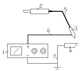
[0021] Such as figure 1 As shown, a controllable nanofluid droplet spray cutting device of the present invention includes a cutter 4 and a charging nozzle 3, and the material of the cutter 4 is hard alloy or high-speed steel. The charging nozzle 3 is located next to the cutter 4. The cutter 4 is connected to the positive output terminal of the adjustable high-voltage electrostatic generator 1 through a wire 7 and grounded. The charging nozzle 3 is connected to the negative output terminal of the adjustable high-voltage electrostatic generator 1 through a high-voltage cable 6. The high-voltage electrostatic generator 1 provides the charging nozzle 3 with a DC negative high voltage. The rear end of the charging nozzle 3 is connected to the micro-injection pump 2 through the silicone rubber tube 5 , the micro-injection pump 2 delivers nanofluid to the charging nozzle 3 , and the outlet of the front end of the charging nozzle 3 faces the cutter 4 .

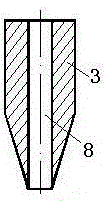
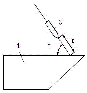
[0022] Such as figure 2 As ...


PUM


Abstract

The invention discloses a cutting method and device capable of controlling spraying of nanometer fluid droplets in the field of cutting cooling and lubricating. A cutter is connected to the anode output end of an electrostatic generator with adjustable high voltage through a wire and grounded, a charging spray nozzle is connected with the cathode output end of the electrostatic generator with the adjustable high voltage through a high-voltage cable, the rear end of the charging spray nozzle is connected with a micro-injection pump through a silicon rubber tube, the micro-injection pump conveys nanometer fluid to the charging spray nozzle, the electrostatic generator with the adjustable high voltage provides direct-current negative high voltage for the charging spray nozzle, positive charges opposite to the charging spray nozzle in polarity are induced on the surface of the cutter, a high-voltage electrostatic field is built up between the spray nozzle and the cutter, the nanometer fluid droplets fully play a role in cooling and lubricating a cutting area, and the effects of cooling and lubricating the cutting area can be improved; by changing the electrostatic field between the spray nozzle and the cutter, the size, the distribution and the motion trail of the nanometer fluid droplets can be adjusted and controlled, and therefore the nanometer fluid droplets can be transported to the cutting area in a directional and controllable mode.

Description

technical field [0001] The invention relates to the field of machining cooling and lubrication, in particular to a nanofluid droplet spray cutting method and device. Background technique [0002] Machining is the main method of obtaining parts. In the cutting process, most of the energy consumed to remove the material is converted into cutting heat and concentrated in the cutting area, causing high temperature of the tool, resulting in rapid tool wear. This is more prominent in high-speed, high-efficiency cutting. In the past, a large amount of cutting fluid was usually poured into the cutting area to reduce the cutting temperature, prolong the life of the tool, and improve the processing efficiency. However, due to the high pressure at the contact interface between the tool and the chip, and the tool and the workpiece, when a large amount of cutting fluid is poured into the cutting area, the cutting fluid that can enter the cutting area and actually play a cooling and lub...

Claims


Application Information

Patent Timeline
Patent Type & Authority Patents(China)
IPC IPC(8): B23Q11/10
CPCB23Q11/1046B23Q11/1061
Inventor 苏宇赵忠超陈丹丹刘志强李碧曹卉宫乐
Owner JIANGSU UNIV OF SCI & TECH
Why Eureka
Eureka Blog
Learn More